Superb stuff again.A few pics of mine so far...
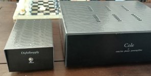
Case:


External transformer and MC loading plugs


Base drilled for ventilation:

Loads of good looking builds starting to appear now.
@scotty38
It's a real beaut.
I have some questions if you don't mind my asking:
1. What's the power cable cover and how did you fasten the connector and strain relief to it?
2. What is the power connector at the signal box? A form of XLR?
3. Love the power switch (and that it mounts in a round hole). What switch is that?
4. How did you mount the phono jacks onto the wood case? I don't see any visible means of support.
On that last, back before time began I had the problem of mounting simple uninsulated jacks that (I was told) had to be insulated from the chassis. My solution was to mount the jacks on unclad epoxy board and then punch larger corresponding holes in the chassis panel with a Greenlee punch. A couple of bolts secured the jack assembly to the panel. I only made one (small and inconsequential) slip up in the array of 10 jacks. Pretty good for a centre punch and a hand-held drill.
Signal grounding in accordance with best practices was then possible. I think I got that right.
Today I have a set of Eichmann's brilliant new "Classic Harmony" outside nut jacks to do the job with one 10mm hole per jack. But I don't think they'd work in 19mm hardwood!
@mhenschel - thank you!
Let me try and answer the questions....
1. The power cable is made from stripped existing cables and then heatshrinked along its length and then covered in the ABS sleeving from HiFi Collective. The strain relief is just a rubber boot I robbed from an RCD I removed from a water pump (The RCD meant I couldn't run the pump off a timer, as it "tripped" each time the power cut, so I replaced it with a normal plug). Sleeving:
ABS Expandable Sleeving (acoustic dampener) | Hifi Collective
2. The connector is a multipole Aviation connector, 6 way:
TP20 Multipole Aviation Connector 250 volt 7-15A Gold Plated Contacts 2 - 6 Pin | eBay
3. The switch is actually square behind the front and is one I "robbed" from an old unused mains extension I had in the workshop. Cannot tell you any more than that I'm afraid.
4. The phonos are mounted using the normal nuts that they come with, the same way as usual. Looking from the rear they are recessed into the woodwork, the recess being maybe 6/7mm wider in diameter than the plugs but but deep enough to allow the threaded part to poke through enough to take the nuts as normal. There is a second hole, drilled in the centre of the recess for the threaded part if that makes sense. I'll try and take a closer picture... pictures and words.....
Hope that helps but if not shout up and I'll try again 🙂
@scotty38
That was informative. Thanks.
Impressive drilling precision for the jacks. Forstner bits? Plunge router?
That was informative. Thanks.
Impressive drilling precision for the jacks. Forstner bits? Plunge router?
Thanks and have to say the woodwork and the drilling of it wasn't done by me. That was done by Ant of BTE Designs. The rest is all my bodgery though 🙂
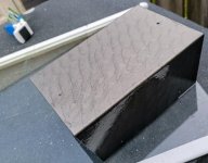
Gave my donor chassis a cosmetic update. This is where I'll be putting the Bigbottle Phonostage in. When just painting...the inconsistency from one part to the other was unbearable..could not get it looking good. Because of the hammerite-isch qualities...So it would have dark streaks from the brush. Then I thought...what if. I'm quite happy with the result. Pity about the chips in the frontpanel...not sure there is a fix. Perhaps a black marker...
Attachments
Last edited:
Looks fine to me!Gave my donor chassis a cosmetic update. This is where I'll be putting the Bigbottle Phonostage in. When just painting...the inconsistency from one part to the other was unbearable..could not get it looking good. Because of the hammerite-isch qualities...So it would have dark streaks from the brush. Then I thought...what if. I'm quite happy with the result. Pity about the chips in the frontpanel...not sure there is a fix. Perhaps a black marker...
How ot sounds is all that matters [emoji6]
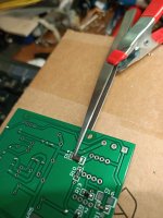
861c - so small
How on earth is it possible to solder on this tiny baby.?
Is there a secret or special technic?
How on earth is it possible to solder on this tiny baby.?
Is there a secret or special technic?
I use reading glasses of 3 times magnification. And to be able to work at higher than table level, I use a box on which I work. Then I use a tweezer with a clamp. And patience. And a soldering iron with a small tip and thin solder wire.
Attachments
Last edited:
Add some solder to one pad firstHow on earth is it possible to solder on this tiny baby.?
Is there a secret or special technic?


So where does the earth line that comes from the tonearm go to? The chassis?
+1 to this question. I was also wondering if there is any recommended grounding scheme for the board, safety gnd / PE, signal ground, and the PCB. I noticed smangus' build at https://www.diyaudio.com/forums/ana...honostage-builders-thread-29.html#post6208019 had one of the standoffs going to chassis earth, along with safety earth. Would be great to get some clarification on whats recommended.
Thanks!
Greg
Been thinking about this,do I ommit the middle connection and use the two outer ones or??Yes it's a 115 115 traffo so you have to common the centre pair, this gives you 230v input.
The way I do it is to create a Chassis Ground, for the ground wire of a tonearm cable.
So, your EARTH wire off the IEC goes to a bolt, which should be fastened to the chassis base using star washers underneath the screw head.
If you have an Earth wire on your transformer, put that on the same bolt too, but the EARTH wire from the IEC should be at the very bottom, making sure the lug is touching the chassis base.
Then, fit a 4mm ground post to the back of your BB3, for the ground wire. Make sure the ground post and your earth connections are on the actual metal of the case, rather than any paint or anodising. You may have to scratch the surface coating off around the underside of where the nut tightens on the ground post.
Check the ground post and the Earth bolt are connected to each other using the chassis, by using a multimeter.
This arrangement is hum free in my system.
Last edited:
Correct. You omit the middle connection for 230V duty.Been thinking about this,do I ommit the middle connection and use the two outer ones or??
- Home
- Source & Line
- Analogue Source
- Bigbottle Phonostage Builders thread