Hi everyone!
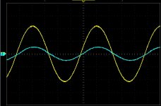
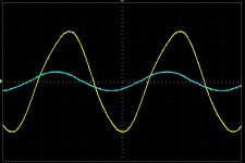
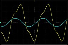
I am writing here because I have a strange problems with my tube amplifier. I attached some screenshots. First one is at 1kHz at 40W power (I am building 40W amplifier), second one is at 20kHz @ 40W and last one is at 63W. As you can see I have a big distortion at 20kHz.The distortion is visible from 17kHz.
This distortion is from power stage. I already checked drivers and phase inverter and everything is OK. First I thought that this is a slew rate distortion because of big input capacity (miller, stray..) of power tube. I am using the 6L6 valves. So I build a strong phase inverter with cathode followers or phase inverter with ECC82 with quiescent current about 5mA per triode but there was no change in the waveforms.
It was measured without any feedback. Waveforms at the output from phase inverter were undistorted - nice and clean. The power stage is classical push-pull, no connection errors.
A also checked if there is some DC current fluctuation at 20kHz but nothing. Power valves are perfectly balanced - I measured bias current Iavg with RIGOL oscilloscope.
Do you know what can be a problem? Output tranny? At low frequencies is everything OK.
Thank you very much!
Best regards,
Maros
Attachments
Last edited:
hello ,
possible to valve ( multi valve ) so burn out to high fréquency or oscilled to parasite , so you possible adjoint the shéma for idéa to research your problem !
😉
possible to valve ( multi valve ) so burn out to high fréquency or oscilled to parasite , so you possible adjoint the shéma for idéa to research your problem !
😉
Hi,
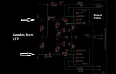
here is my power stage. Nothing special for now. Valves are biased to 50mA quescient current. Plate voltage is 400V. I am using an ultralinear connection - I also tried to unconnect 470Ohm resistros from transformer taps and to connect them to +400V but it is the same.
Primary impedance is 5200Ohm (Raa)
Attachments
Last edited:
How's the wave at 10W?
At lower output power is it much smaller, but still I can see a small amout of distortion. But it is definitely better!
I also measured voltage at plates of 6L6 and this voltage has distorted high peaks. Low peaks seems to be fine.
Next time please post FULL schematic, not just part of it.
From what I see I can guess its a Mullard 520 type amplifier with considerable amount of GNFB.
I suspect high level of distortions at frequencies above 17KHz are caused by large leakage inductance/low resonant frequency of the output transformer.
From what I see I can guess its a Mullard 520 type amplifier with considerable amount of GNFB.
I suspect high level of distortions at frequencies above 17KHz are caused by large leakage inductance/low resonant frequency of the output transformer.
Next time please post FULL schematic, not just part of it.
From what I see I can guess its a Mullard 520 type amplifier with considerable amount of GNFB.
I suspect high level of distortions at frequencies above 17KHz are caused by large leakage inductance/low resonant frequency of the output transformer.
I cannot send a full schematic because it is big and I think it is not important. I checked previous stages and distortion doesnt exist in these stages. When I am driving power stage as I showed to you in the schematic my phase inverter doesnt clip and waveform is beautiful 🙂
It is not a Mullard, it is my own amplifier.
The output transformer was designed by me, so I probably made a mistake. Today I will try to measure resonant frequency, leakage inductance and capacity of primary winding. Thanks!
I have seen similar (but not quite as severe) performance with an output transformer built by a reputable supplier well know on this forum. At high frequencies even starting at 15 kHz the distortion increased at around 3W. This is all by memory from a number of years ago. So I would agree this is OPT effect.
31.5 watts per tube seems like a lot for 6L6's. My McIntosh MC40 amps use 2 6L6's per monoblock to make 40 watts. But you designed this amp so I'm sure you know a lot more than I do.
BillWojo
BillWojo
OK, I made some measurements.
Primary inductance: L1 = 30H (secondary is opened, 1kHz)
Leakage inductance: Ls = 25mH (secondary is shorted, 1kHz)
Resonant frequency: 1700Hz (secondary is opened)
From resonant frequency and primary inductance I calculated:
capacity of primary winding: C1 = 302pF
I never did these measurements before. This is my first push-pull amplifier. My prievious single-end amplifier and SE output transformers were OK.
When I measure resonant frequency with 8Ohm load resistor in secondary so resonant frequency is about 39kHz.
My question is:
Is my problem with distortion at high frequency definitely from output transformer? I could not find any information about high-end transformers and their parameters.
I have 4 sections of primary and 3 sections of secondary. Order from core is:
P
S
P
S
P
S
P
Thank you,
Maros
OK, I made some measurements.
Primary inductance: L1 = 30H (secondary is opened, 1kHz)
Leakage inductance: Ls = 25mH (secondary is shorted, 1kHz)
Resonant frequency: 1700Hz (secondary is opened)
From resonant frequency and primary inductance I calculated:
capacity of primary winding: C1 = 302pF
Maros
25mH leakage inductance is a way too much for amp with GNFB.
Even 12.5mH is quite problematic, 10mH is more or less OK, 8.5mH is fine.
My question is:
Is my problem with distortion at high frequency definitely from output transformer?...
I would say yes, it seems so.
But, please measure the frequency the response (from 1kHz...50kHz).
This will tell a lot.
Raa,
regarding your BIAS... 😀
just IMHO, in case your POT (R90) goes ... you should connect the two resistors R86/R91 also to the negative voltage otherwise your tubes will 😱
Cheers
Hp
regarding your BIAS... 😀
just IMHO, in case your POT (R90) goes
... you should connect the two resistors R86/R91 also to the negative voltage otherwise your tubes will 😱Cheers
Hp
There is nothing wrong with the bias arrangement. R90 acts as bias balance pot.
Completely normal circuit.
Completely normal circuit.
I would say yes, it seems so.
But, please measure the frequency the response (from 1kHz...50kHz).
This will tell a lot.
Hi,
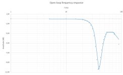
this is frequency response from 1kHz to 90kHz..
Attachments
Raa,
regarding your BIAS... 😀
just IMHO, in case your POT (R90) goes
Cheers
Hp
Yop, I understand what you are saying. But I am measuring the quescient current by MCU and when for any reason the quescient current will go up (abnormally) I will turn off a plate voltage.
And artosalo is right. It is for bias balance.
A few observations...
The Primary Inductance is not a fixed constant... It will climb and then roll off with respect to applied signal level..what level did you measure at ??
30H is very low... Are you using E-I laminations ???
The capacitance will change according to signal level as well....depending on the di-electric material used....since di-electric is not "really" a constant it has a gradient with respect to frequency and applied voltage gradient...
The key question I have... did you use the "Dynaco" winding arrangement for your UL transformer ?? That patent has long run out...but the winding sections are in PARALLEL ...and if you missed your turn count on one of the sections then you can get AC cross currents between the sections, which can make for some problems...
Also that arrangement made use of reverse winding the center section and then hooking up the start and finish reverse....
Remember that when measuring leakage inductance you will need to subtract the DC resistance vector from the complex vector to get your imaginary vector... The Total DC resistance is the secondary DC resistance reflected to primary + the primary DC resistance.. thus you have a r+jw that may appear larger then the actual leakage...
Last edited:
..this is frequency response from 1kHz to 90kHz..
Quite typical response, found from Hammond and Edcor too.
Anyhow the harmonics above 10 kHz can not be heard.
I think more important is the low end preformance, at 20...100 Hz.
Concerning your power target, I have built several 6L6 (5881) UL-PP amplifiers with 450 V supply and 6k6 OPT.
Typically I get some 35 W, not more. So your target is maybe too high.
Last edited:
Sorry for that. It was measured with Chroma LCR METER 11021 at 1V voltage level, 1kHz.A few observations...
The Primary Inductance is not a fixed constant... It will climb and then roll off with respect to applied signal level..what level did you measure at ??
Yes. And yes, 30H is quite low, I was calculating about 60H and more, but theory is theory 🙂30H is very low... Are you using E-I laminations ???
The capacitance will change according to signal level as well....depending on the di-electric material used....since di-electric is not "really" a constant it has a gradient with respect to frequency and applied voltage gradient...
The key question I have... did you use the "Dynaco" winding arrangement for your UL transformer ?? That patent has long run out...but the winding sections are in PARALLEL ...and if you missed your turn count on one of the sections then you can get AC cross currents between the sections, which can make for some problems...
Also that arrangement made use of reverse winding the center section and then hooking up the start and finish reverse....
Honestly, I dont know about Dynaco winding patent. My 3 secondary sections are connected in parallel. 4 primary sections are connected in series. Center tap is in the middle of bobbin. For one plate it goes from 1 section (which is closer to core) and then to 2 section (which is at the top of winding or the most futher from core). For second plate it goes from centre tap to 3 section (which is futher from core) to 4 section which is the most close to core. Each section is connect "in phase" - I mean from start of 1section to end of section 4.
Could you send me a information about Dynaco winding?
Remember that when measuring leakage inductance you will need to subtract the DC resistance vector from the complex vector to get your imaginary vector... The Total DC resistance is the secondary DC resistance reflected to primary + the primary DC resistance.. thus you have a r+jw that may appear larger then the actual leakage...
yes of course but my method is fast and the error is not so big.
Last edited:
Quite typical response, found from Hammond and Edcor too.
Anyhow the harmonics above 10 kHz can not be heard.
I think more important is the low end preformance, at 20...100 Hz.
mmmmm, yes, you are right! But you know... I am very unsatisfied with this waveform.
Concerning your power target, I have built several 6L6 (5881) UL-PP amplifiers with 450 V supply and 6k6 OPT.
Typically I get some 35 W, not more. So your target is maybe too high.
I will pull my target down but for know I will do everything for 35W 🙂
- Status
- Not open for further replies.
- Home
- Amplifiers
- Tubes / Valves
- Big distortion of tube amplifier at high frequencies