Just a thought: perhaps there are some very high frequency oscillations in your amp. By very high, I mean 100-200 kHz or so. Try some snubber circuits (~1-2nF cap and ~5-10k resistor in series) on the OPT, between each plate and B+ center tap.
This happened to me too (although I'm was using some TV sweep tubes).
This happened to me too (although I'm was using some TV sweep tubes).
To me, it looks like slew-induced distortion: @ 20KHz, the output voltage lags the input drive by almost 90°.
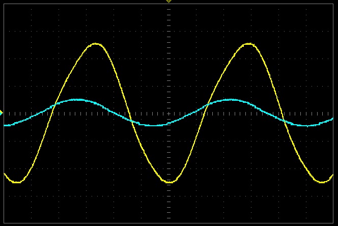
This means that the load impedance is dominated by capacitance, and the tube's current struggles to charge and discharge this capacitance.
I do not see exactly why the current should be limited in a non-linear fashion by the tube, but I am not a tube expert.
The symptoms however seem clear enough.
It would be interesting to have a look at the cathode current by placing the probe on the 1R5 resistors
Where could this capacitance come from? the estimated transformer capacitance seems too small to explain the effect, but distributed capacitances can sometimes induce effects unexpected from the equivalent lumped value
Last edited:
To me, it looks like slew-induced distortion:
20KHz, the output voltage lags the input drive by almost 90°.
This means that the load impedance is dominated by capacitance, and the tube's current struggles to charge and discharge this capacitance.
I do not see exactly why the current should be limited in a non-linear fashion by the tube, but I am not a tube expert.
The symptoms however seem clear enough.
It would be interesting to have a look at the cathode current by placing the probe on the 1R5 resistors
Where could this capacitance come from? the estimated transformer capacitance seems too small to explain the effect, but distributed capacitances can sometimes induce effects unexpected from the equivalent lumped value
The capacitance you are talking about is input capacitance of the power pentode (Cag, Miller capacity, stray capacitancies..). Slew rate distortion occurs when previous stage (driver, phase inverter) doesnt has enough current to charge and discharge this capacity.
I also tried this and I builded a strong phase inverter with cathode follower which has an output resistance around 1kOhm.
EDIT: I definitely tried it - LTP with cathode follower with quescient current of cathode follower about 5mA which is so much I think for pair of 6L6
Last edited:
I am not talking about the input capacitance: problems at this level would also show in the drive waveform.
I am thinking of the load (output) capacitance, although the the exact mechanisms remain unclear to me.
If it is output-related, it should show in the cathode current
I am thinking of the load (output) capacitance, although the the exact mechanisms remain unclear to me.
If it is output-related, it should show in the cathode current
If it is output-related, it should show in the cathode current
How exactly?
In principle, the waveforms should reflect the class (A)B operation of the stage: nice complementary half-sinusoids on each cathode.How exactly?
If the circuit struggles in some way, you'll see something resembling more trapezoids than sine arches, tending towards squarewaves if the frequency (and stress) is increased.
This would indicate that the available current is limited in some way.
It could be related to the plate to screen voltage ratio, not kept within correct limits by the transformer.
The screen grid could also be involved in other ways, via its current for example. As I said before, I am no expert enough in tube details to detect exactly what's going on, but there is a bottom line: the circuit has to obey the basic Kirchoff's laws, and this doesn't leave many possibilities open for distortion mechanisms.
The speeds involved are much, much lower than what a naked tube is capable of, and this means that there is some "stolen" current going somewhere where it shouldn't.
A bit of detective work is needed, and any information might prove useful: voltages on each electrode, before and after stoppers to detect any abnormal current, etc. Once you have the full picture, you'll hopefully have the lightbulb moment, when everything falls in place...
I checked cathode current before two days and I saw nice half-sinusoids at 1kHz and 10kHz. At 17kHz-20kHz there was some problem and half-sinusoids were distorted. But this was not a new information for me, because I still dont now why. Yes, it should be from slew-rate thing, but my quescient current is about 50mA per 6L6. I think that is a quite high number... The capacitance should not be higher as:
C = Ia / 2*pi*f*Vpeak = 0.05 / 6.28*20000*300 = 1.32nF
I measured 302pF at 1kHz. Capacitance will change with higher driving signal, but strange behavior starts earlier... hmmmmmm
C = Ia / 2*pi*f*Vpeak = 0.05 / 6.28*20000*300 = 1.32nF
I measured 302pF at 1kHz. Capacitance will change with higher driving signal, but strange behavior starts earlier... hmmmmmm
If I understand correctly, you calculated capacitance from the primary resonant frequency? Does this include primary to secondary capacitance?
All good fortune,
Chris
All good fortune,
Chris
If I understand correctly, you calculated capacitance from the primary resonant frequency? Does this include primary to secondary capacitance?
All good fortune,
Chris
Yes, I measured the primary inductance and resonant frequency when the secondary is opened. Do you know some other/better way how to calculate the capacitance of the primary winding?
Yes, I measured the primary inductance and resonant frequency when the secondary is opened. Do you know some other/better way how to calculate the capacitance of the primary winding?
No, your method is great. I'm just worried about the parasitic capacitances from primary to secondary. This appears in some smeared/distributed way as an additional load to the output tubes.
All good fortune,
Chris
Yes, I measured the primary inductance and resonant frequency when the secondary is opened. Do you know some other/better way how to calculate the capacitance of the primary winding?
Did you mean Leakage inductance was measured with shorted secondary...?
Then you measured the resonant freq with open secondary ?
Did you mean Leakage inductance was measured with shorted secondary...?
Then you measured the resonant freq with open secondary ?
Leakage inductance was measured with shorted secondary and I was measuring inductance on the primary side.
Winding capacity was measured with opened secondary -> It was measured primary inductance and resonant frequency and from thomson equation was calculated C.
Leakage inductance was measured with shorted secondary and I was measuring inductance on the primary side.
Winding capacity was measured with opened secondary -> It was measured primary inductance and resonant frequency and from thomson equation was calculated C.
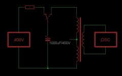
One way to measure resonance .....
You charge a large known cap and dump it on the primary winding with a fast switch.....pulsed step ... Then examine the ring frequency on the scope...
Usually use a FET as the switch.....sometimes I trigger it from FO cable if the voltages are very high...
Is this a transformer you designed and wound ??
If so, if you don't mind...what is core size and total primary turns..???
Core material I assume is a M6 or M3 ??
As for open primary inductance....you mentioned 30H .....but that was at very low voltage and may not be valid.... Keep in mind that the Dynaco 431 ultra-linear OT had about 900 to 1100 Henries of L over it's operating range...
This required approx 1800 turns for that 2" stack..
One way to measure resonance .....
You charge a large known cap and dump it on the primary winding with a fast switch.....pulsed step ... Then examine the ring frequency on the scope...
Usually use a FET as the switch.....sometimes I trigger it from FO cable if the voltages are very high...
Do you think something like this? (Attachement)
Is it better way how to measure resonance? My method gives a big errors? Is the capacitance of the capacitor so important that it must be known? Because when resonant frequency is the ring frequency on the OSC... why known capacitance?
Is this a transformer you designed and wound ??
If so, if you don't mind...what is core size and total primary turns..???
Core material I assume is a M6 or M3 ??
Yes and it has about 3200 turns of primary winding. I didnt wind it. Core material - i dont know - but my demand was grain oriented, 4% silicon steel. Do you think that they fooled me with core material?
Attachments
- Status
- Not open for further replies.
- Home
- Amplifiers
- Tubes / Valves
- Big distortion of tube amplifier at high frequencies