I used the suggested circuit but I'm connecting the op-amp to the wrong place - I know this because changing resistor values makes no difference! Or perhaps a Vbe doesn't belong in the design.Determine the current through the transistor, eg 10mA.
Determine the beta of the transistor, eg 100.
The base current will be 0.1mA.
The current through the (variable) resistors should be small compared with the collector current.
The base current should be small compared with the current through the resistors.
The optimum resistorcurrent is collector current divided by the square root of beta.
With the given values, Ir =1mA.
You can try this circuit and adjust the values as required.
Attachments
You missed the point, that a current must flow through vbe multiplier. Add a resistor to positive voltage from vbe multiplier collector ,like in your previous circuit with diodes.
Dunno what I smoked last night - I must try inhaling it next time...
I knew what I had done wrong when I awoke this morning LoL
I knew what I had done wrong when I awoke this morning LoL
Placed in 1.2K resistors to correct my omission and placed a 10u cap in parallel (mimicked this from another circuit).
Qspice sim shows no anomalies so I think I'm ready to build on a breadboard to test. Many thanks to all.
The output devices might not be ideal, as mentioned, for 10W rated speaker. I'd be open to suggestions for improved hi-fi.
BTW, for DIY speaker fans I'll be publishing an article in a few weeks about bracing to maximize the efficacy of the speaker baffle.
The method is unique and will provoke discussion. It's inspired by 'Single Degree of Freedom' concepts for structural dynamics: driver resonance is returned to the baffle rather like closed-loop feedback. Draft available if interested.
Last edited:
Whatever, but the circuit... view of #41 it is all very... wearisome. Elaborate on a proper way less sqeezed view. Next to nobody follows.
Rules, being the road, or the drawing of circuit diagrams, are the common platform of civilisation.
errrr...
Rules, being the road, or the drawing of circuit diagrams, are the common platform of civilisation.
errrr...

Determine the current through the transistor, eg 10mA.
Determine the beta of the transistor, eg 100.
The base current will be 0.1mA.
The current through the (variable) resistors should be small compared with the collector current.
The base current should be small compared with the current through the resistors.
The optimum resistorcurrent is collector current divided by the square root of beta.
With the given values, Ir =1mA.
You can try this circuit and adjust the values as required.
May I ask how one determines the current through the resistors? Say from the datasheet or a measurement at some point? I'm having trouble understanding how the values you gave are determined using the above information.Determine the current through the transistor, eg 10mA.
Determine the beta of the transistor, eg 100.
The base current will be 0.1mA.
The current through the (variable) resistors should be small compared with the collector current.
The base current should be small compared with the current through the resistors.
The optimum resistorcurrent is collector current divided by the square root of beta.
With the given values, Ir =1mA.
You can try this circuit and adjust the values as required.
Here is my result with help of previous replies and more reading on the subject.
I've tested the attached which I've run in Spice sim reading Ib at 430mV and quiescent current at 20mA with 49Ohms dialed in to a virtual pot. Would a 500Ohm cermet pot be a suitable choice? My solution looks rather simple - comments welcome.
Cheers
I've tested the attached which I've run in Spice sim reading Ib at 430mV and quiescent current at 20mA with 49Ohms dialed in to a virtual pot. Would a 500Ohm cermet pot be a suitable choice? My solution looks rather simple - comments welcome.
Cheers
Attachments

Last edited:
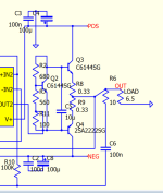
If with q3 you tried vbe multiplier, then emitter must go to base of q2. Now you are shorting base-emitter and q3 not functions at all.
Actually resistor values are both very low (R3 , R14), and q3 may not conduct at all, and bias voltage would be current dependent. I would suggest increase them 10 times.
Interesting exercise.
With R3 @ 1K, R14 @ 549 Quiescent current is 660mA; placing these in reverse order then Quiescent current becomes 25mA.
This is unexpected. The VBe multiplier reads 430mV at collector and emitter and 120 to base. Does this sound right? Might I need a different part for Q3?
With R3 @ 1K, R14 @ 549 Quiescent current is 660mA; placing these in reverse order then Quiescent current becomes 25mA.
This is unexpected. The VBe multiplier reads 430mV at collector and emitter and 120 to base. Does this sound right? Might I need a different part for Q3?
502mV results in a Re 120mV, Quiescent current 125mA. I read that 25mV is a good target, am I correct? I'll concluded that a Vbe multiplier is not suitable.Base - emitter at lowest should be 0,5v .
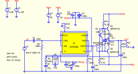
I did simulate in QSpice biasing with diode and pot. Curiously, I get the best result with just one diode! Could I be on the wrong path?
Q current is 25mA and load over the diode is 5mA. R13 will be a cermet pot. Thanks for the previous help.
Attachments
Important is quiescent current itself on output emitter resistors,not a millivolts, whose can be suggested for different schematic with different transistors and different value resistors. Sometimes increasing idle current makes very small improvement, so 25ma is a good starting point.
Resistor in series with diode is used , but i think this is not optimal, because voltage on resistor is more current dependent, than on a diode. Better try differentl diode type.
Resistor in series with diode is used , but i think this is not optimal, because voltage on resistor is more current dependent, than on a diode. Better try differentl diode type.
Is a diode selection that then requires a resistor of increased value what I should aim for?
Spice shows that with UF1001 diode I need 86.6 Ohms for Ie (Q1) 21mA. Is this the right direction ?
Is a log or linear pot best suited?
Many thanks
Spice shows that with UF1001 diode I need 86.6 Ohms for Ie (Q1) 21mA. Is this the right direction ?
Is a log or linear pot best suited?
Many thanks
In simulation diode forward voltage may differ from real diode, also it's not identical in all diodes of same type. If simulation shows a requirement of resistor, try another type diode, with higher forward voltage. As example higher voltage ones. Or maybe two schottky in series like 1n5818.
I've learned much, thanks.
Keeping that diode and reducing both R6 and R7 to 1.5K creates a 23mA idle current without resistor pot adjustment.
Keeping that diode and reducing both R6 and R7 to 1.5K creates a 23mA idle current without resistor pot adjustment.
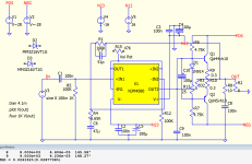
Following previous suggestions
with R6 / 7 @70K; R9 / 10 @1 ohm the base to emitter now measures 498mV (compared to 410mV before). Quiescent current is 50mA. The resistor values seem higher than examples I've seen. Does anyone see any issue that I might have missed. Is the 1N4148 diode suitable?
Thanks.
with R6 / 7 @70K; R9 / 10 @1 ohm the base to emitter now measures 498mV (compared to 410mV before). Quiescent current is 50mA. The resistor values seem higher than examples I've seen. Does anyone see any issue that I might have missed. Is the 1N4148 diode suitable?
Thanks.
Attachments

- Home
- Amplifiers
- Solid State
- Biasing target for push-pull amp