The output needs two stages of emitter followers, the second using power transistors, and a trimpot to adjust the bias.
Ed
Ed
So I can learn, what's your evidence? What you wrote doesn't address the question!Such transistors will magic smoke with load chosen.
Transistors 2N3904 or 2N2222 not able to handle 6 ohms load you have specified . In simulation software this is not checked , there's no parameter like transistor power specified for spice , so in simulation it would work ,but in practice not . As was just suggested ,these small power transistors can control more powerful ones ,but not directly drive such load .For load like 1k they would be fine .
My mistake . You meant not 2N2222 , but 2SA2222 (those popular numbers), which is much more powerfull ,but still not best choice for audio use , because its rated only 25W ,designed for switching applications,not continuous linear application like amplifier .The same about 2SC6144, only 25W rated .
For biasing you can try various variants ,vbe multiplier would be not optimal there, because it has no midpoint,so you will have unsymetrical clipping . With diodes would work ,but need to ensure that transistors would not conduct too much .But resistors base-collector (2.2k in your schematic) would limit output current heavily ,and you will not get highest power possible .Try to add additional transistors ,to reduce base current and load to opamp , and use 3-4 diodes in series ,connect op amp output to mid point of diodes .At first practical test to prevent smoke use small power resistors in series with power supplies (something like 10 ohms 0.25W),and check if they not becoming hot or smoke .Its tricky to get proper idle bias current ,when not possible to adjust it ,only by trying various diodes and measuring what idle current you get .Transistors must be placed on heatsink.
For biasing you can try various variants ,vbe multiplier would be not optimal there, because it has no midpoint,so you will have unsymetrical clipping . With diodes would work ,but need to ensure that transistors would not conduct too much .But resistors base-collector (2.2k in your schematic) would limit output current heavily ,and you will not get highest power possible .Try to add additional transistors ,to reduce base current and load to opamp , and use 3-4 diodes in series ,connect op amp output to mid point of diodes .At first practical test to prevent smoke use small power resistors in series with power supplies (something like 10 ohms 0.25W),and check if they not becoming hot or smoke .Its tricky to get proper idle bias current ,when not possible to adjust it ,only by trying various diodes and measuring what idle current you get .Transistors must be placed on heatsink.
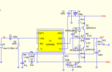
I selected different transistors. I am still learning about biasing and, from various sources, I came up with this (attached). With Spice I can measure current of 2.9mA through the diodes; from emitter to Re 27mV (26 and 28). I still haven't found a way to attach an ammeter to QSpice.
I am wondering if this resembles something worthwhile testing on a breadboard? I have no plan to add drivers; the op amp's current output is enough for the selected BJTs. Some mentioned earlier to add a trim pot...that's beyond my breadth of knowledge design wise but would be happy to learn.
I am wondering if this resembles something worthwhile testing on a breadboard? I have no plan to add drivers; the op amp's current output is enough for the selected BJTs. Some mentioned earlier to add a trim pot...that's beyond my breadth of knowledge design wise but would be happy to learn.
Attachments
The link is a definition of a rubber diode (Vbe multiplier), I'm no further forward in determining the values of resistors to bias a 10W audio amp.Replace D1 and D2 with a Vbe multiplier.
What I know is V is +28 -28, 6.5V Load, Re will likely be 0.33 ohms and someone mentioned emitter to Re should be about 20 - 25mV.
If a Vbe method is used, or diodes, my question remains how does one determine the values of the resistors? YouTube videos, so far, haven't been helpful.
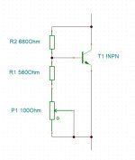
Determine the current through the transistor, eg 10mA.
Determine the beta of the transistor, eg 100.
The base current will be 0.1mA.
The current through the (variable) resistors should be small compared with the collector current.
The base current should be small compared with the current through the resistors.
The optimum resistorcurrent is collector current divided by the square root of beta.
With the given values, Ir =1mA.
You can try this circuit and adjust the values as required.
Attachments
The optimum resistorcurrent is collector current divided by the square root of beta.
I've never seen this recommendation before, but it seems quite reasonable. Can you advise me of the underlying math? Thanks!
Best regards,
Steve
No, pure intuition, but the explanation is already in #29.the underlying math
I've been busy with this thing for the last odd thirty years.
There is more hidden then visible with this very compact circuit.
It's the single solid state equivalent of the 555.

This is very helpful, thanks. I'll run some permutations in SPICE.Determine the current through the transistor, eg 10mA.
Determine the beta of the transistor, eg 100.
The base current will be 0.1mA.
The current through the (variable) resistors should be small compared with the collector current.
The base current should be small compared with the current through the resistors.
The optimum resistorcurrent is collector current divided by the square root of beta.
With the given values, Ir =1mA.
You can try this circuit and adjust the values as required.
I volunteered to captain a special interest group at the local Mens-Shed - were gonna each build an amp.!
Edit: I'm out of my depth! Do I delete the resistors R11 and R13?
I'm also happy to learn the method to bias with diodes too.
Last edited:
@Citizen124032
Thanks for the explanation. Unfortunately QSpice doesn't have a trim pot! No ammeter either. TINA and PSpice install with errors, won't play nice!
I'm back to the original question about diode biasing resistor values. Was my latest diagram worthwhile testing on a breadboard?
You can try microcap also.
You don't need ammeter in spice, current can be calculated by knowing voltage drop on a resistor, 0,33 ohms in your case. I = U /R . Assume 0,05V drop on 0,33 ohms. 0,05/0,33=0,151 Ampere. Every simulation program miss some of components , whose are present on another app. But for playing you may use similar opamp,or different, and compare differences.
You don't need ammeter in spice, current can be calculated by knowing voltage drop on a resistor, 0,33 ohms in your case. I = U /R . Assume 0,05V drop on 0,33 ohms. 0,05/0,33=0,151 Ampere. Every simulation program miss some of components , whose are present on another app. But for playing you may use similar opamp,or different, and compare differences.
Terry2000, you accidentally hit the bold B! Or there is a reference into it to... Monthy Pythons Spanish Inquisition?
Anyhow, the trimpot is a to determine value of a fixed resistor in Qspice. I'm using Aimspice (thanks Trond!) for over thirty years, and is text based input with nice graphical outputs. Very elaborate but forces the user not to make errors.
Tina has good simulation features - the scope is very nice (no install issues here...). Pspice I've never used.
Consider the output transistors running at a higher current then the diodes. So, their Vbe's is higher then the Vd's.
Without an extra resistor in series with the two diodes, Q1 and Q2 are pretty much closed and the amp operates in class B.
The value of this extra 'in series resistor' depends on the actual current through the diodes and the extra voltage needed to put Q1 & Q2 into small biased class AB. That extra voltage is the higher Vbe to open Q1 & Q2 and the voltage drop over R9 & R10 times the bias current.
Bias current through Q1/2 say 50mA, the Vbe's at 0.75V. Voltage drop over R9/10 is 50mA * 2 *0.33 = 33mV (not very much!).
Total needed bias voltage at the bases: 1.533V.
Current through the diodes D1/2 say 10mA, the Vd at 0.7V.
Needed 'extra' voltage over a series resistor: 1.533 - 1.4000 = 0.133V.
The resistor must be 0.133V / 10mA = 13.3Ω -> {12E0 <> 15E0}.
Using a 47E potmeter (actually a variable resistor!), logaritmic preferred, will set the proper bias setting.
This is all linear math, you should be able to determine all correct values yourself.
Things become 'out of balance' as soon as a modulating signal is applied, but that was the initial condition to aim for.
Next: how to keep things as much as possible in balance, in control, with as little as possible distortion.
The pile of books written about this subject spans the perimeter of the earth...
Attachments

I suspect Terry2000 is asking for guidance in choosing R11 and R13 in the schematic contained in post 26.
Depends of the values of 'pos' & 'neg'.
As long as not all information available is shared, one can only assume, presume, project, estimate or even predict.
Have all in one informative landscape sized letter or A4 overview. Then answers flow in.
Science is not about solving puzzles. That's what those SI guys expects. With their measures.
As long as not all information available is shared, one can only assume, presume, project, estimate or even predict.
Have all in one informative landscape sized letter or A4 overview. Then answers flow in.
Science is not about solving puzzles. That's what those SI guys expects. With their measures.
Many thanks for the explanations to date. BTW, I experience Dyscalculia. I've no fear of stepping out of my comfort zone, or should say my Comfy Chair, but I haven't had to read algebra for 50 years... now it's my new challenge!
As I only need a 10W amp I plan to use a T0-220 package transistor with an opamp for the driver (for now). Simulations without biasing diodes (pure Class B) show a very good sine wave with just the tiniest wiggle at the X-over and 0.14 THD. With diodes the THD drops by a magnitude so nice to have, I thought. However, I had chosen an unsuitable diode in earlier circuit posted. Now with standard diodes meaurements are closer to what one would expect; I had created the problems myself! How to mount diodes to the heatsink poses a challenge so the Vbe method is what I'll try first.
D Self's books are out of budget for my retirement hobby and the tutorials I found on biasing, to date, have been examples with a 9V battery and small signal device for 1W mono. However, with the input from all who posted to my question I can take my project a step forward so thanks all very much. Allow me to post some questions again should I stumble. Cheers!
You're welcome! I think you can benefit from reading. Amplifier design is a century-old problem about which much has been written.
Ed
Ed
Post your calculated Vbe multiplier and questions.I can take my project a step forward... Allow me to post some questions again...
There's a smart compensation (in the collector) to improve it to - I leave that to others.
- Home
- Amplifiers
- Solid State
- Biasing target for push-pull amp