I have created a 10W amp (2.5A) in QSpice and I'm preparing to build a prototype on Perfboard.
My question is what should I target for the current across the diodes?
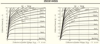
I have attached datasheet screenshot. My interpretation is I'll only need 7mA which seems too low.
Please take a look at the datasheet and advise me if I've got this calculation wrong.
Both hFE and fT are over 270mA and 270MHz respectively.
Also, I have the option to use dual channel. Advisable or superfluous?
Many thanks for reading.
My question is what should I target for the current across the diodes?
I have attached datasheet screenshot. My interpretation is I'll only need 7mA which seems too low.
Please take a look at the datasheet and advise me if I've got this calculation wrong.
Both hFE and fT are over 270mA and 270MHz respectively.
Also, I have the option to use dual channel. Advisable or superfluous?
Many thanks for reading.
Attachments

Thanks you Ed. Unfortunately I don't find it easy to write a simulator to solve the equation numerically. I'm a novice: Is this done using SPICE?Read my article on Class AB Biasing.
Ed
My question was: Have I read the datasheet properly to arrive a 7mA for the resistors/diodes the BTJs I'm using. Or can one actually use the datasheet to determine the mA target to start testing?
I wrote the software. Programming is one of the things that I do.
The optimal bias for class AB push-pull BJTs will have ~22mV across one of the emitter resistors. This holds true for all BJTs and resistor values. In a power amplifier, the typical bias current will be 50-100mA.
Ed
The optimal bias for class AB push-pull BJTs will have ~22mV across one of the emitter resistors. This holds true for all BJTs and resistor values. In a power amplifier, the typical bias current will be 50-100mA.
Ed
Thank you Ed.The optimal bias for class AB push-pull BJTs will have ~22mV across one of the emitter resistors. This holds true for all BJTs and resistor values. In a power amplifier, the typical bias current will be 50-100mA.
Ed
The output of the op-amp 4580 I'll use is 50mA - I'll start with that current.
If I parallel the dual channels I'm guessing this current will double.
Have you any knowledge of this - could it be of benefit?
Thanks again
Op-amps cannot be connected in parallel. Your amplifier needs two stages of emitter followers after the op-amp.
Ed
Ed
Either Ed or I misinterpret the question. Is it about the output devices or the diodes/VBE multiplier?
The collector and emitter of Q4 appear to be swapped in the schematic of post #9, and the transistors are incorrectly drawn as Darlingtons.
Thanks, everyone, for your inputs. For 10W to 8ohm speakers with the 4580 capable of pushing out 50mA (single channel) I plan to connect it to the output devices: 2SC6144SG / 2222SG. The circuit is a mashup from reading Rod Elliot's examples and watching JohnAudioTech al' Youtube.
What is missing from the examples I've been copying is the current calculation through the diodes. How it is derived interests me.
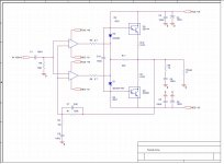
An old (20 years ago) article I found by BurrBrown gives an example of configuring a dual channel IC in parallel to a single output. I wondered if it could be beneficial or just superfluous for such a low power amp?
What is missing from the examples I've been copying is the current calculation through the diodes. How it is derived interests me.
An old (20 years ago) article I found by BurrBrown gives an example of configuring a dual channel IC in parallel to a single output. I wondered if it could be beneficial or just superfluous for such a low power amp?
Attachments

Worth repeating that you cannot use opamps in parallel like this, each opamp needs a separate, independent negative feedback path. Trying to use one shared feedback path will ensure the opamp outputs are completely different and one or both will saturate hard to the rails.
The variation in device input offset voltage might only be a few 100µV, but multiply that by the opamp open loop gain and you might have something like 10V to 1000V theoretical difference in output voltages.
The variation in device input offset voltage might only be a few 100µV, but multiply that by the opamp open loop gain and you might have something like 10V to 1000V theoretical difference in output voltages.
Interesting: TI or AD give examples of paralleling dual channel op-ams wth 100ohm res to bias each channel while another manufacturer gave 2.7ohm. They say this is a way to get more current gain ( get 50mA from a single channel so would more be an advantage was my question).Worth repeating that you cannot use opamps in parallel like this, each opamp needs a separate, independent negative feedback path. Trying to use one shared feedback path will ensure the opamp outputs are completely different and one or both will saturate hard to the rails.
The variation in device input offset voltage might only be a few 100µV, but multiply that by the opamp open loop gain and you might have something like 10V to 1000V theoretical difference in output voltages.
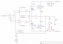
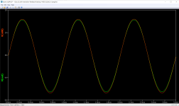
SPICE sim shows me a minor difference to output V swing with each channel paralleled to single output: attached screenshot shows RED before closing in feedback and GREEN at the load. Granted that's a sim - reality might be different.
With the help provided so far I'll go ahead and wire up to a test board and take real-world measurements.
Attachments
I suggest you post a schematic of the circuit you plan to breadboard. Yes, you can share opamp drive, but it's not trivial. The parallel connection of opamp sections shown in earlier posts will not work even with 2.7 ohm or 100 ohm resistors in series.
Instaed of paralleling opamp outputs, just add emitter followers, and adjust biasing circuit accordingly. Thus much more that 100 ma you trying to reach will be possible.
Thanks to All. I've got the information I need to start the prototype on my breadboard and test.
I also need more experience with SPICE sim but I should use a new thread for SPICE question.
Cheers!
I also need more experience with SPICE sim but I should use a new thread for SPICE question.
Cheers!
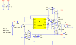
Redesign:
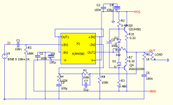
First stage is a buffer and second is emitter follower using op-amp as driver (it gives 50mA). X-over dist is gone.
I would like feedback on my choice of resisters for the diodes.
As per graph placing cursor over the diodes shows 7mA with 250mA over the transistors (I don't know how to configure an ammeter using SPICE). Am I close to something that won't produce magic smoke when wired to a breadboard?
Thanks
Attachments
- Home
- Amplifiers
- Solid State
- Biasing target for push-pull amp