the rating is only for the first caps.if i remember correct. since most 5Kv caps i've seen had 220 input and wheere only rated 400 or so.Pretty much 🙂, although if you only plan on using a 5 stage multiplier to get 5kV you will be running the parts right at their 2kV rating. Remember caps and diodes in multipliers see twice the peak input voltage during operation. I would recommend upping the voltage rating on the parts to 3kV or consider using a few more sections on the multiplier. Also, the 0.01uF cap size is a bit overkill when used with the HF oscillator. 2200pF will work just fine and are a bit cheaper at the higher voltage ratings.
BTW, this is essentially what the EMCO modules have inside them. It is just a bit cheaper when you construct them yourself.
ALso, your mentioning the 555 timer reminded me of this post:
http://www.diyaudio.com/forums/planars-exotics/190716-esl-power-supply-question-6.html#post3744943
Perhaps move discussion of your HV supply to your ESL build thread?
if you use a CF inverter to feed the caps, they need to be higher voltage since the start voltage is higher then 230. more in the region of 500 or so.
i might be wrong but this is how all the cascades are build i've seen, no one uses the rated output voltage as value for the caps. its a waste of money
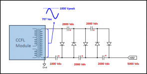
bengel is wanting to use a CCFL to drive a 5 stage multiplier to get 5kV.... no one uses the rated output voltage as value for the caps. its a waste of money
In this case, each capacitor and diode(except for the first one) will see 2kV across it during operation.
Normal voltage rating recommendation for multiplier parts is twice the peak input voltage.
You might check out this design guide from Vishay.
http://www.vishay.com/docs/88842/anusingr.pdf
Attachments
bengel is wanting to use a CCFL to drive a 5 stage multiplier to get 5kV.
In this case, each capacitor and diode(except for the first one) will see 2kV across it during operation.
Normal voltage rating recommendation for multiplier parts is twice the peak input voltage.
You might check out this design guide from Vishay.
http://www.vishay.com/docs/88842/anusingr.pdf
ahaa, ok nice ! thx bolsert. so they where not far off with 400 🙂 be it 40 volts.
so hes feeding a 700 volts into the caps ? thats pretty high. so there are 2 ways to do this either go more stages more ripple but more controll you could go higher if needed on the output voltage or go less stages, less ripple more costs and less over voltage. good to know ! 🙂
So best would be less stages, ripple wise, but cost effective would be more stages and feed the caps less. then question is are 2 cheaper caps same priced as one with higher rating 🙂. well it is something to think about and something i will think about at my next design THX!
Last edited:
Yes ~700Vrms...pretty much what Acoustat used in all their supplies....so hes feeding a 700 volts into the caps ? thats pretty high.
ML uses 450Vrms in their latest HV supplies which use a CCFL type oscillator.
One thing that is nice about the CCFL DC-to-AC converter is that the output voltage is proportional to input voltage. So you can easily vary the output voltage of your HV supply from 1kV to 5kV without changing number of multiplier stages. It also makes incorporating feedback regulation of the voltage fairly easy if you are so inclined.
Yes ~700Vrms...pretty much what Acoustat used in all their supplies.
ML uses 450Vrms in their latest HV supplies which use a CCFL type oscillator.
One thing that is nice about the CCFL DC-to-AC converter is that the output voltage is proportional to input voltage. So you can easily vary the output voltage of your HV supply from 1kV to 5kV without changing number of multiplier stages. It also makes incorporating feedback regulation of the voltage fairly easy if you are so inclined.
yes this is what i use as well simple adapter and a simple voltage regulator in front of the CCFL , so you got a save way of building it in something without having to deal with regulation concerning high lethal voltages. just low voltages and high voltage without juice.. (at least depending on witch CCFL 🙂 used ofcourse)
- Status
- Not open for further replies.