I am presuming the turn on voltage level is irrelevant (as long as it is under a few thousand volts 🙂 ).
I was going to use this one and panel mount it to the speaker box.
http://www.mouser.com/Search/ProductDetail.aspx?R=4700A3
I was going to use this one and panel mount it to the speaker box.
http://www.mouser.com/Search/ProductDetail.aspx?R=4700A3
Yeah, that was my 1st pick (because it is so much cheaper 🙂 ) but like the panel mount option better.
looks like this well work....?
thanks
https://www.radioshack.com/products/radioshack-120vac-neon-lamp-assembly-2-pack?variant=5717312581
thanks
https://www.radioshack.com/products/radioshack-120vac-neon-lamp-assembly-2-pack?variant=5717312581
bolserst.........you have my trust...you have raised my understanding of all things ESL..or any other subject ..that I have read your info, input on....your memory is over the top!
but I have to tell you ...how I see it...when I am in a room were speakers are playing ....I am in the signal path.....my ESL bias point
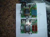
For years now I have been buying older Martin logans an reworing the panels when I can.....over 10 pr.... in all the pic I can find....of the ML bias boards
look at this pic...of my latest ML finds... bias board....the one with the brown caps came out of a $10k pr of ML Prodigy...an is in all others ML I have found...back to 1995...not the cls..clx...
the bias board with the blue cap came out of a pr ML Ascent floor models I pic up for a song...... these blue caps give a sound...I have never heard out of any ML....not just one mans opine..
So from what Iam hearing..an others...night an day diff ...only thing diff in the boards is the caps... what added too the bias setup... CAN make the sound of a ESL....
I know the a diff cap can change the voltes....but that still changes the sound....right
Your a physic guy...I get it..an try to live there my self.....but I can hear big diff in the sound of any thing I do to the ESL bias.... with all do respect!...thanks for just being there..an yes I well speak for others...gladly
but I have to tell you ...how I see it...when I am in a room were speakers are playing ....I am in the signal path.....my ESL bias point
For years now I have been buying older Martin logans an reworing the panels when I can.....over 10 pr.... in all the pic I can find....of the ML bias boards
look at this pic...of my latest ML finds... bias board....the one with the brown caps came out of a $10k pr of ML Prodigy...an is in all others ML I have found...back to 1995...not the cls..clx...
the bias board with the blue cap came out of a pr ML Ascent floor models I pic up for a song...... these blue caps give a sound...I have never heard out of any ML....not just one mans opine..
So from what Iam hearing..an others...night an day diff ...only thing diff in the boards is the caps... what added too the bias setup... CAN make the sound of a ESL....
I know the a diff cap can change the voltes....but that still changes the sound....right
Your a physic guy...I get it..an try to live there my self.....but I can hear big diff in the sound of any thing I do to the ESL bias.... with all do respect!...thanks for just being there..an yes I well speak for others...gladly
Attachments
Sorry, still pondering this 🙂.
Say the light is on and thus my diaphragm charges up to 4000V...then the light goes off. How much of a voltage drop must the diaphragm experience before the light turns on again and charges it back up to 4000V? Presuming the bulb trigger voltage is 100 VDC, would it be 4000V-100V = 3900V ??? i.e. it "bounces" back and forth between 3900V - 4000V.
Say the light is on and thus my diaphragm charges up to 4000V...then the light goes off. How much of a voltage drop must the diaphragm experience before the light turns on again and charges it back up to 4000V? Presuming the bulb trigger voltage is 100 VDC, would it be 4000V-100V = 3900V ??? i.e. it "bounces" back and forth between 3900V - 4000V.
With my Acoustat 2+2s.....I can pull the ac on my bias .......an at med loudness...I get output for 3-5 min.... with out much loss in loudness output.....we well just have to see....hear this setup....don't go I wont know....
Hi,
yes, that is the way it works.
When the voltage difference between supply and membrane reaches the treshold voltage of the lamp, the lamp fires and recharges the membrane.
So the membrane voltage 'bounces' slowly up and down.
One last remark:
The lamp's firing treshold (say 94V) is typically specced in the DS.
If the lamp fires, it doesn't burn till the voltage over its pins drops to 0V, but it switches off somewhere between 50-60V.
Taking the above example the membrane voltage never reaches the 4kV of the supply but would 'bounce' between ~3.90kV and ~3.95kV.
jauu
Calvin
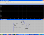
I agree...usually see voltage across neon lamps ramping between “strike” voltage level of about 95V and “extinction” voltage level of about 65V. If you are so inclined, LTSpice includes a neon lamp model in which you can define these voltage levels and the on-resistance. It will give you a feel for how the blink rate changes with component values and, unfortunately, bias voltage. If you increase bias voltage you will notice blink rate increases. This does not mean the resistance of the leakage paths have changed, just that the leakage current is increasing since it is proportional to applied voltage.
The attached LTSpice screen capture shows sim for the default neon lamp model parameters of 100V & 50V. Notice the 100K resistor in series with the neon lamp. You can use a resistance here to increase the “extinction” voltage if you want to try and minimize the amplitude of the voltage cycling. The downside is that the “ON” flash of the neon lamp gets shorter and fainter when resistance is added; blink rate also increases. If the resistor is too high in value, the lamp will dimly flicker at a high rate which is not useful for monitoring leakage currents.
@ bengel/tyu
Note that the panel mount neon lamps you guys posted links for include a resistor in series with the neon lamp inside the assembly. Depending on the value of this resistor, you may need to bypass it to get an easily seen blink indicator.
Attachments
Wouldn't this "oscillation" be a bad thing? i.e. wouldn't the spl be, in effect, "modulated" by the changing diaphragm charge? If there was leakage (always is) and you just had it hooked up directly to the 10 MOhm EHT output, the voltage would stay the same (unless the leak exceeded the current thru the 10 MOhm resistor????).
Sure a 100V oscillation would have almost negligible effect on the SPL though - if I did the math.
Sure a 100V oscillation would have almost negligible effect on the SPL though - if I did the math.
The 30V variation in bias voltage at a frequency < 1 Hz would cause the sensitivity of the ESL to slowly ramp up and down by less than +/- 0.05dB; less variation for higher bias voltages. So, not really a concern, but easily bypassed with a jumper when not testing for leakage if it bothers you. Like tyu I find the flashing can be distracting if visible from the listening position.
If you have significant leakage in your panel, most ladder multiplier supplies will have supply ripple of similar or larger amplitude even without the neon lamp circuit...and this ripple is varying at audio frequencies so more of a concern from modulation standpoint.
If you have significant leakage in your panel, most ladder multiplier supplies will have supply ripple of similar or larger amplitude even without the neon lamp circuit...and this ripple is varying at audio frequencies so more of a concern from modulation standpoint.
Last edited:
Absolutely. If a different capacitor (type or value) results in different bias voltage, this would be noticeable as a change in the ESL sound. My experience is that if you adjust the input voltage for two different bias supplies such that the output voltage reaching the panel was the same, the type and/or value of capacitors made no noticeable difference in sound.…I know the a diff cap can change the voltes....but that still changes the sound....right
Just pulling the AC plug allows the panels to keep using the energy stored in the HV supply multiplier capacitors.With my Acoustat 2+2s.....I can pull the ac on my bias .......an at med loudness...I get output for 3-5 min.... with out much loss in loudness output..
How long do the panels keep playing if you disconnect the panels from the bias supply?
This would be the indication of how much leakage your panels have.
If you have significant leakage in your panel, most ladder multiplier supplies will have supply ripple of similar or larger amplitude even without the neon lamp circuit...and this ripple is varying at audio frequencies so more of a concern from modulation standpoint.
Just curious, could this be mitigated by using large caps in the ladder? (i.e. reduce ripple)
ML setup there bias with a 200v trans.....there bias is 3k60v...caps are .1mf 660v............
Acoustat bias trans 750vre ....bias is 5kv...caps are 3k .0033....biger cap sound better to me....
Acoustat bias trans 750vre ....bias is 5kv...caps are 3k .0033....biger cap sound better to me....
If all you are concerned about is ripply, you only need to upsize half of the capacitors.The only downside is 3kV+, .1uF caps are not cheap 🙂
http://www.diyaudio.com/forums/planars-exotics/190716-esl-power-supply-question-6.html#post3772446
Increasing the frequency of the voltage applied to the voltage multiplier and/or using fewer sections in the multiplier also reduces the ripple and allows use of much smaller capacitors. This is why I recommend using a CCFL HV oscillator to drive the multiplier rather than the more traditional 50 or 60hz wall powered supply.
http://www.diyaudio.com/forums/planars-exotics/190716-esl-power-supply-question-5.html#post3714088
Taking a step back though, this discussion of supply ripple is mostly just academic.
If your ESL is leaky enough to be putting ripple in the HV supply, it would probably be best to fix the leak.
But for those who wear belt and suspenders... 😉
Hmmm, interesting... Funny, I was just thinking along these lines last night thinking about using a 555 timer.
Forgive me, as my electronics knowledge is somewhat weak but you are saying take something like this:
CXA M10M L TDK DC to AC Inverter for Non Dimming Type Cold Cathode Lamp CXAM10ML | eBay
Feed it DC (like 12V or something), take that output (which I think is something like 1 kV) and run it through a ladder..... So if you need 4 kV you need 4 "steps"..... And you need >1 kV caps & diodes to handle it???
So, yes, you answered my question a few years ago 🙂
http://www.diyaudio.com/forums/plan...nel-efficiency-first-build-9.html#post3471237
http://www.diyaudio.com/forums/plan...nel-efficiency-first-build-9.html#post3471237
So to summarize... 🙂
This: http://www.mouser.com/ProjectManager/ProjectDetail.aspx?AccessID=35096d16f4
+
This: New LM317 Adjustable Voltage Regulator Step Down Power Supply Module LED Meter | eBay (x2)
+
This: wall worts, current limiting resistors etc....
= 2 adjustable bias supplies capable of running up to 5 kV ????
(and I apologize for hijacking the OP's thread 🙂 ).
Last edited:
Pretty much 🙂, although if you only plan on using a 5 stage multiplier to get 5kV you will be running the parts right at their 2kV rating. Remember caps and diodes in multipliers see twice the peak input voltage during operation. I would recommend upping the voltage rating on the parts to 3kV or consider using a few more sections on the multiplier. Also, the 0.01uF cap size is a bit overkill when used with the HF oscillator. 2200pF will work just fine and are a bit cheaper at the higher voltage ratings....2 adjustable bias supplies capable of running up to 5 kV ????
BTW, this is essentially what the EMCO modules have inside them. It is just a bit cheaper when you construct them yourself.
ALso, your mentioning the 555 timer reminded me of this post:
http://www.diyaudio.com/forums/planars-exotics/190716-esl-power-supply-question-6.html#post3744943
Perhaps move discussion of your HV supply to your ESL build thread?(and I apologize for hijacking the OP's thread 🙂 ).
- Status
- Not open for further replies.
- Home
- Loudspeakers
- Planars & Exotics
- Bias Supply