Any CFP-schematic that I should search for to get a view??
Rod Elliott's P3A is a classic example of this. It's also a very simple design which can make it easier to see what's doing on. There's also quite a few threads on this forum discussing it.
One important qualifier:
We have been discussing EF output stages... Using a single heatsink is for EF output stages (and its derivatives)
For CFP output stages, the drivers should not be on the same heatsink as the output devices and the bias generator device should be thermally coupled to the drivers, not the output devices.
Yes - CFP is another kettle of fish (I have no experience with those).
Non est tantum facile. Have you tried this out in real life? I have devoted too many brain cells to this and loadsa solder too .. when commercial amp design & production was important to me. It's sorta 'true' in theory but when theory & practice don't coincide ... 😎For CFP output stages, the drivers should not be on the same heatsink as the output devices and the bias generator device should be thermally coupled to the drivers, not the output devices.
I spent a long time trying to make CFP amps 'work' but eventually gave up. The bias instability is only one con. A more important one was the propensity to self destruct when overloaded at HF.
Self came across another con in his book (can't remember which edition). The low level THD of a CFP is MUCH higher than EF2. I asked him if he would investigate this for his new book but nothing heard. These days I'm a beach bum ... so don't pay too much attention to my ravings 🙂
The topic is really quite complex and there are solutions which 'work' though they don't conform to 'accepted' theory. That's why I suggested the test in #41. If that's OK, then the EXACT method .. including mounting and positioning of drivers, heatsinks, sensors will give OK results.hcpower said:One question: Aragon (by Mondial) made several amps with separate heatsink for the drivers.... Is a main heatsink really that important in real life? Not to neglected, but DIY'ers tempts to be very specific even into very small details
Don't imagine an amp liked by da Golden Pinnae must be good. In da previous Millenium, I tested many Golden Pinnae amps in DBLTs. Many (all?) sounded different from 'good' amps. When I investigated these different sounding amps, the reason was always gross ... xover distortion, instability with real speaker loads, insufficient or liquid BS, bla bla ... 😱
That should be Golden Pinnae amps with CFP O/P stages. 🙂This happens in many (all?) Golden Pinnae amps with complemenatry O/P stages.
The test I describe in #41 will show very small bias immediately after heating up and lasting for a minute or more. If you measure 1W THD in that period, it may be more than 1% .. all nasty xover. 😱
No wonder Golden Pinnae amps sound different. 😀
Just some observations: when I built a Gemini-like amplifier, the quiescent current appeared stable with the drivers/bias clamped between two small aluminium angle pieces.
But I never particularly liked the sound. Didn't have any means of measuring distortion at the time, but always used EF afterwards.
Also in building quad-303-like amps, I found it necessary to clamp the pre-drivers and bias regulators in similar small aluminium brackets. That was my first observation that a triple - even the Quad NPN/PNP/NPN and PNP/NPN/NPN was not going to be as stable "as stated on the tin" - If I recall correctly the suggestion in Quad blurb that thermal connection "wasn't necessary", I found it was.
I suspect that bias current instabilty in a CFP is likely if the output transistor heatsink is not large enough.
Additional stability can be achieved by adding resistors in series with the emitters of the drivers. This increases the bias voltage needed in the Vbe multiplier, hence increases the compensation ratio.
Also, the somewhat pernicious HF instabilities that can occur in CFP stages can sometimes be ameliorated by such degen. resistors.
Last edited:
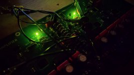
Finally started som proto building... Couldn't wait, and only had Dale's around! Might order a bunch of cheap resistors 🙂
The predivers and drivers has meen attached to the main heatsink, and the PNP at BIAS is on top of the PCB.
View attachment 1092027
The predivers and drivers has meen attached to the main heatsink, and the PNP at BIAS is on top of the PCB.
View attachment 1092027
Attachments
Last edited:


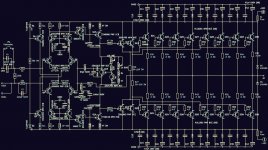
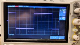
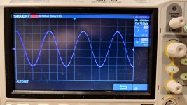
Ok, so the project has started with some proto-PCB 🙂 ... I've skipped the DC-servo in favour of a simple RC-feedback network, but that aside I followed the schematic with a fine squarewave using the NPN-BIAS...
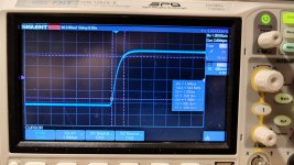
I now come to the testing of the PNP+NPN-BIAS, and it works (also!)
But, is there a way to calculate the 4Vbe's or what to measure?
I use 10k pot + 220ohm in the PNP as shown and recommended earlier in this thread
I now come to the testing of the PNP+NPN-BIAS, and it works (also!)
But, is there a way to calculate the 4Vbe's or what to measure?
I use 10k pot + 220ohm in the PNP as shown and recommended earlier in this thread
Attachments

- Home
- Amplifiers
- Solid State
- BIAS network recommendations