In the absence of a manufacturer's recommendation is there a way to determine optimum bias adjustment settings?
In general, enough to minimize distortion without overheating. But if you can elaborate I'm sure someone can give more specific recommendations.
Depending on the amp, messing with the bias too much from what it was designed for may make it prone to oscillation. But yeah, going by heat sink temperature is a good start.
Measure voltage drop across emitter/ballast resistors and do the Math.
Aim for, say, 30 mA per power transistor.
As in: 10mV across 0.33 ohm=30mA
Aim for, say, 30 mA per power transistor.
As in: 10mV across 0.33 ohm=30mA
A big problem with theoretical correct bias and the manufacturers recommended bias is that the amplifier may not have sufficient heat sink capacity to allow the former.
All of you.. many thanks for these contributions!
Very tempted by JM Fahey's suggestion as I've recently installed new output transistors.
Am attaching a picture below and perhaps you could be so kind as to tell me from where to take measurements on this particular board.
It's a Rotel RA-913.
The service manual says:
"adjust to 7.5mV"
AND ALSO
"adjust to 20mV”…?
Which is correct?
Some background:
- All four output transistors recently replaced with:
MJ15022 (formerly 2SC1403A)
- Drivers on left channel replaced with:
KSA1381 and KSC3503
DC offset reads:
3mV Left
6mV Right
Currently heatsinks are cool and after 6 hours the amp is sounding and functioning "fine."
Any likely consequences to running at 7.5mV if 20mV was what Rotel recommended?
Given the recent changes I don’t want to stress the amp but at the same time would like to know that it's running optimally.
Attachments
Previously heard that amps can produce an improved sound quality when the bias is adjusted to a higher level.
However, as previously mentioned, taking this too far will cause problems.
Happy to hear any further advice.
However, as previously mentioned, taking this too far will cause problems.
Happy to hear any further advice.
“Theoretical correct bias” for distortion is something like 26 millivolts across the emitter resistor, with lower resistance values being “better” as long as R is sufficient to prevent runaway. With 0.1 ohm resistors and multiple pairs, that can put you in Krell bias range. Nice for a weenie roast. Usually you strike a compromise where bias is “enough” - the 30 mA total number quoted above works well on vintage equipment and real amplifiers with real heat sinks. If the heat sink is small, you may even have to dial that back. You may get acceptable performance if there is just enough bias to crack the output transistor “on”. Depending on design and what “acceptable” is to you. Output triples can be far more tolerant or less tolerant of bias range than the usual EF2 or QC. Some oscillate wildly if the bias is wrong, others start working well once you crack it “on” and don’t care at all above that.
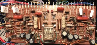
So would one measure at the legs of each of the white rectangular resistors labelled 'MPC71 0.22ohmsK FU824' in the top left and right of the photo?
Attachments
Yes, those white rectangular things are the emitter resistors. Voltage across the resistor and ohm’s law. Use clip leads on your meter so you don’t slip and short something out.
So, power on?
DMM set on the low 200 range?
Measure each pair of legs?
Doesn't matter which way round + and - are connected to the legs?
DMM set on the low 200 range?
Measure each pair of legs?
Doesn't matter which way round + and - are connected to the legs?
This is a quasi amp so bias is lower than fully complementary types. 7.5mV seems right. No need to go above.
Cheers
Cheers
Thanks junior35, interesting.
Post #6 has an attachment from Rotel showing 20mV.
Reflecting on this, do you think they meant start at 7.5mV and then adjust up to 20mV once the amp is warmed up and stable?
Post #6 has an attachment from Rotel showing 20mV.
Reflecting on this, do you think they meant start at 7.5mV and then adjust up to 20mV once the amp is warmed up and stable?
Thanks junior35, interesting.
Post #6 has an attachment from Rotel showing 20mV.
Reflecting on this, do you think they meant start at 7.5mV and then adjust up to 20mV once the amp is warmed up and stable?
Hi,
No,I think it's a typo. You're really measuring bias over one emitter resistor and 7.5mV is enough for this type of topology.
Cheers
Thanks, much appreciated.
So for measuring the voltage drop, set the DMM to 200mV and place + and _ on the legs ether side of the rectangular white resistors. Should they all read the same pretty much?
So for measuring the voltage drop, set the DMM to 200mV and place + and _ on the legs ether side of the rectangular white resistors. Should they all read the same pretty much?
This is a quasi amp so bias is lower than fully complementary types. 7.5mV seems right. No need to go above.
Cheers
A quasi type may also have a different reading on the upper and lower transistors. One side (the fake PNP) will be the driver plus output quiescent current, the other side might only be only the output current in its emitter resistor. An exact schematic will tell you if this actually happens.
The best way to set bias is by measuring THD. If you don't have that capability, rule of thumb for most BJT class AB designs is 25 to 50 mA per output device. That translates into 5 to 10 mV for 0.22 Ohm emitter resistors. (2.5 to 5 mV - 0.10 Ohms, 7.5 to 15 mV - 0.33 Ohms, 10 to 20 mV - 0.47 Ohms). You will need to check the settings you made after a few minutes and keep an eye out for creeping bias. Make small adjustments at a time, sneaking up on the correct setting. Generally waiting 10-15 min with a load connected between adjustments will give you more stable readings. Always disconnect speakers or load when making adjustments. A final check after 30 min is advised. Aim for about 100 to 120 degrees F heatsink temps at idle (no music). Err on the lower end of that scale if the heatsinks are on the smaller side. A final check after 30 - 45 min with the cover back on is smart. Play some music and check heatsink temps one final time. You want to stay under 150 degrees F.
Some amps have switchable bias putting the output stage into a low power class A mode ie. NAD, Nakamichi, Luxman. Thats more of a gimmic in my opinion and just makes the amp run hotter with no benefit to sound. In most cases the amp doesn't have sufficient heatsinking to deal with the extra thermal load over longer periods of time and cooks your electrolytic caps, so I don't recommend using higher bias modes unless you can really detect a sonic benefit.
So basically speaking, going over the recommended bias range on a BJT class AB amp ends up in wasted heat and can make it unstable, creating a thermal instability problem, leading to overheating and also may increase THD. Staying in the 100 to 120 degree window of heatsink temps gives you long term stability and reliability and in most cases the best sound your amp is capable of.

A quasi type may also have a different reading on the upper and lower transistors. One side (the fake PNP) will be the driver plus output quiescent current, the other side might only be only the output current in its emitter resistor. An exact schematic will tell you if this actually happens.
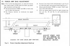
Correct. In this case it's the upper transistor emitter resistor (R639) that's measured between pins 7 and 9.
Cheers
Attachments
- Home
- Amplifiers
- Solid State
- Bias adjustment