one can calculate gm (Yfs) from Idss and Vpinch off.
See Borbely.
i.e. match Idss and then from within those batches select Vpinchoff and you have roughly matching curves.
Ok, thanks for the tip. The hard part is making an adapter board to measure ea SOT23 with clamp pressure. Yfs can also be measured directly with two DMM rig.
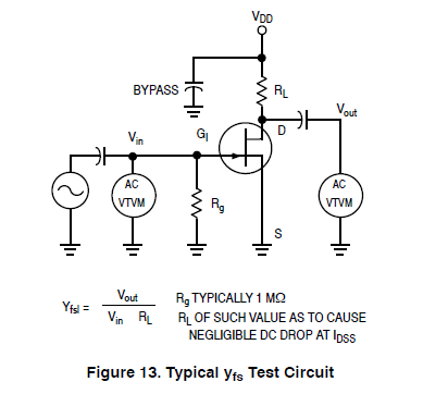
Fig. 13 from here:
http://www.retro.co.za/zs1ke/FT-107/AN211A.pdf
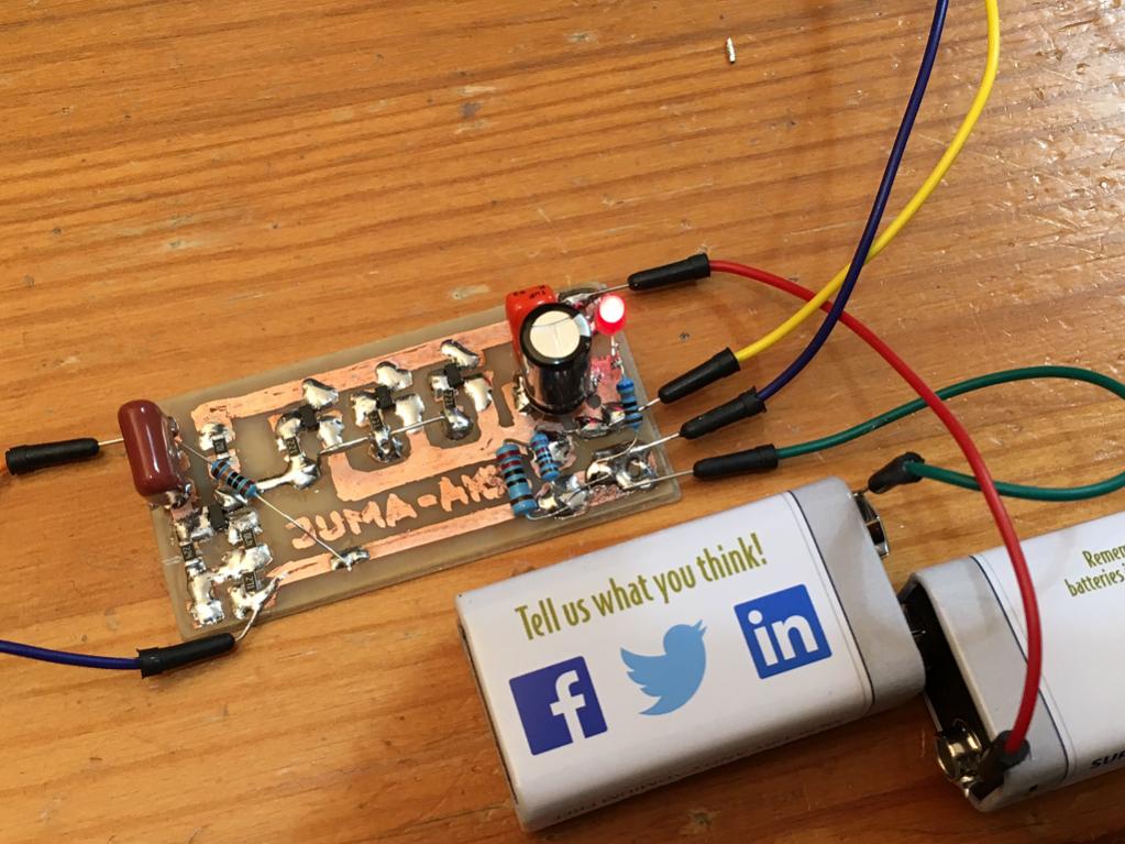
In case anyone missed it, my new amp is now completed and under test. Sounds great.
http://www.diyaudio.com/forums/solid-state/301164-mosfet-source-follower-headamp.html
(adding 270R resistor in parallel to 250R headphone outs made all the difference - beautiful sound)
Attachments
Last edited:
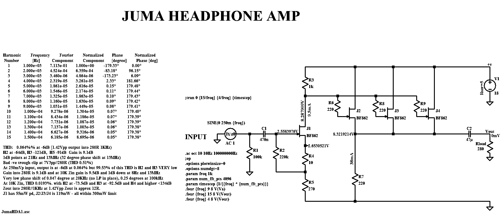
Over in my other thread, Hugh just came up with a slick low parts count BF862 headamp based on Juma's preamp.
http://www.diyaudio.com/forums/solid-state/301164-mosfet-source-follower-headamp-4.html#post4929312
For driving 60ohm cans, add one more output stage and change source resistors to 150R.
This looks very simple and very cool. 🙂
http://www.diyaudio.com/forums/solid-state/301164-mosfet-source-follower-headamp-4.html#post4929312
For driving 60ohm cans, add one more output stage and change source resistors to 150R.
This looks very simple and very cool. 🙂
Over in my other thread, Hugh just came up with a slick low parts count BF862 headamp based on Juma's preamp.
http://www.diyaudio.com/forums/solid-state/301164-mosfet-source-follower-headamp-4.html#post4929312
For driving 60ohm cans, add one more output stage and change source resistors to 150R.
This looks very simple and very cool. 🙂
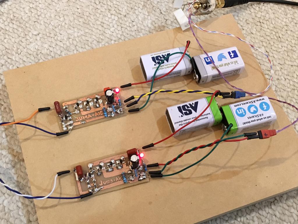
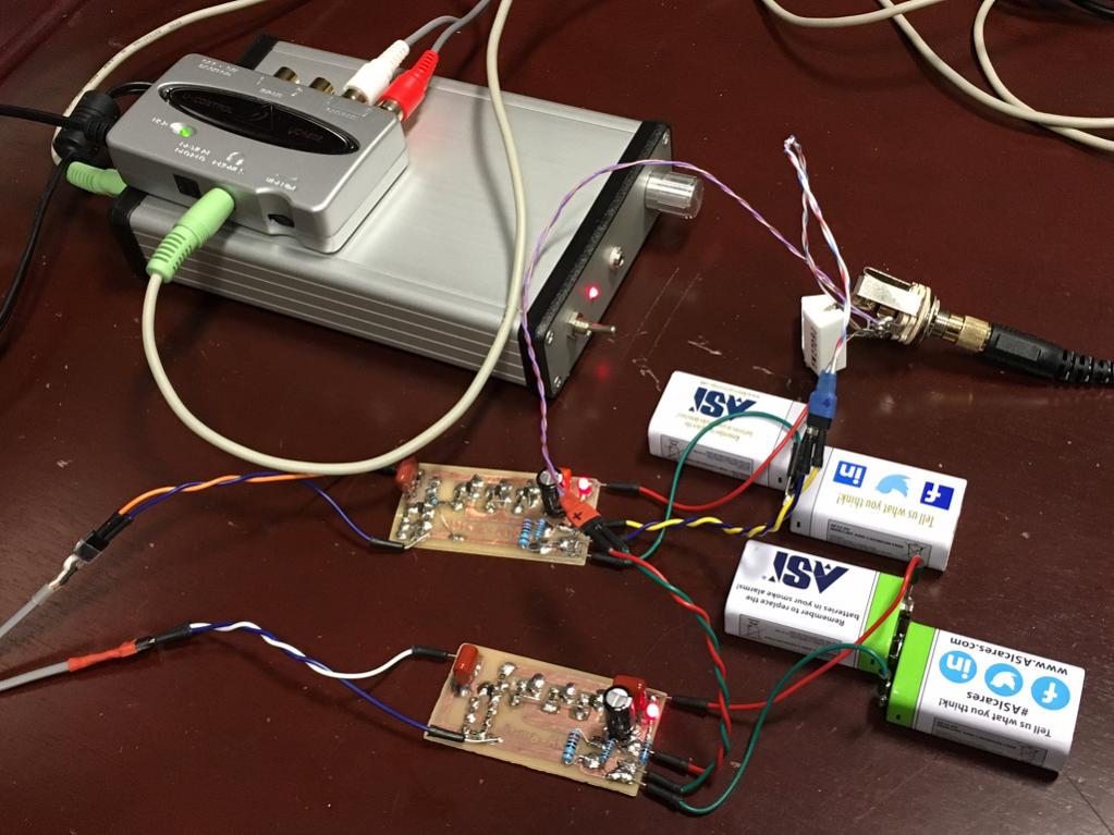
It's singing now.... need second channel for stereo to do sound quality assessment. What I hear so far in one ear is surprisingly good. This Juma-Aksa design is very easy to make. I am using Idss matched JFETs.
More here:
http://www.diyaudio.com/forums/solid-state/301164-mosfet-source-follower-headamp-9.html
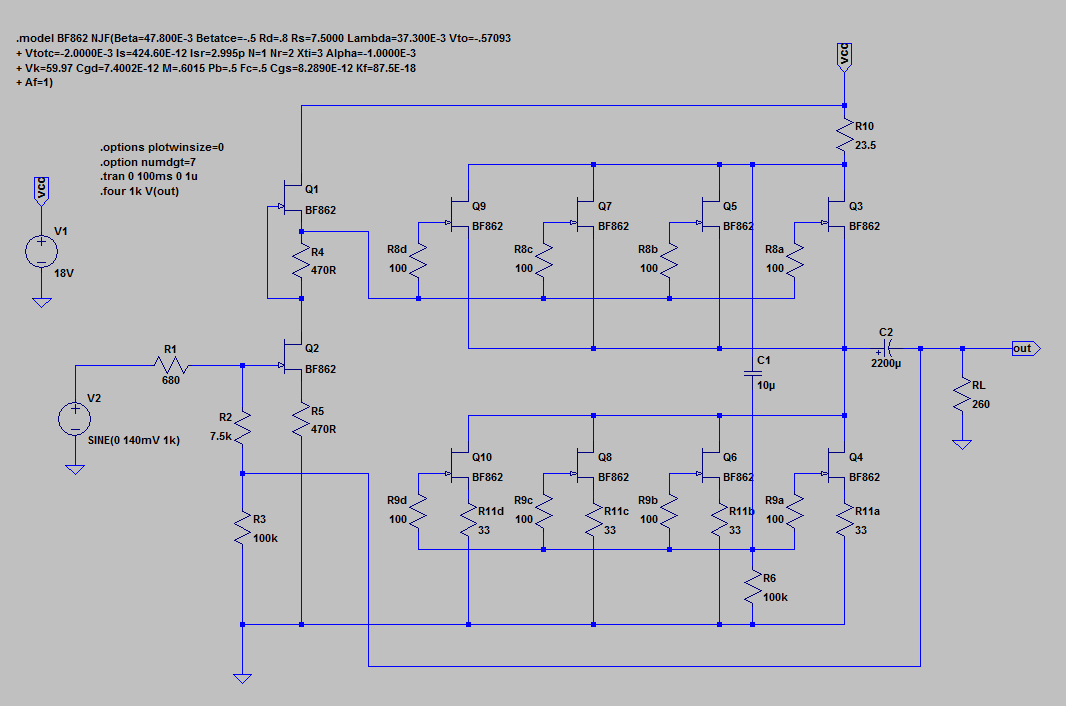
It's pretty amazing what you can do with 4 tinyJFETs. The best part is the predicted harmonic profile having pretty much only H2 at -61dB and H3 at -121dB. I will try a single MOSFET output version with more current capability and no need to match devices.
List of ones to try - all N-channel MOSFETs:
- ZVN4306GTA (20v, 2.1A, 350pF)
- ZXMN6A11ZTA (60v, 2.7A, 330pF)
- BSP129H6327XTSA1 (240v, 350mA, 108pF)
List of ones to try - all N-channel MOSFETs:
- ZVN4306GTA (20v, 2.1A, 350pF)
- ZXMN6A11ZTA (60v, 2.7A, 330pF)
- BSP129H6327XTSA1 (240v, 350mA, 108pF)
Last edited:
AB comparison of above 4 JFET amp with 10 JFET amp here:
http://www.diyaudio.com/forums/solid-state/301164-mosfet-source-follower-headamp-12.html
http://www.diyaudio.com/forums/solid-state/301164-mosfet-source-follower-headamp-12.html
At the end, did you use heat sinking in the JFET's, as we suggested or it wasn't needed?
Wasn't needed. The JFETs are flowing about 12mA or 84mW ea, well below the 300mW rating. They barely feel warm.
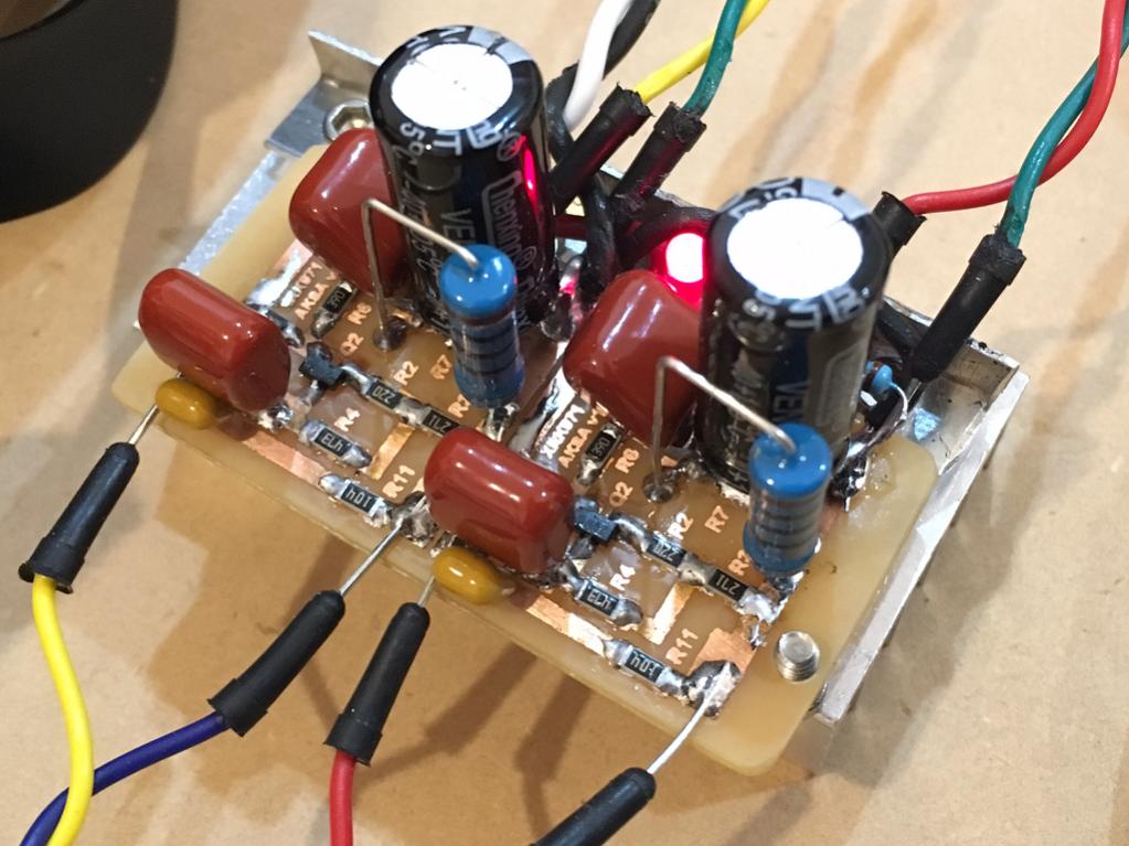
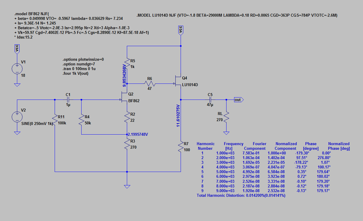
New 2 JFET (BF862 and LU1014D) SE amp with awesome sound.
http://www.diyaudio.com/forums/solid-state/301164-mosfet-source-follower-headamp-15.html#post4933888
http://www.diyaudio.com/forums/solid-state/301164-mosfet-source-follower-headamp-15.html#post4933888
New 2 JFET (BF862 and LU1014D) SE amp with awesome sound.
Will you post the .asc file?
Looks like a source follower, but with gain stage. Yes?
Yes, first source follower provides gain (actually derived from preamp). I will pos LTspice file when I get to a computer.
The second stage is a source follower, or common drain.
The first stage is common source, the source is common to both the input and to the output.
The first stage is common source, the source is common to both the input and to the output.
As built model
In your as-built model, you changed R11a, R11b, R11c, and R11d from 1R to 33R. Was this a model-only change, or did you change this to reduce dissipation through the FETs? I've just started soldering parts on my board, and want to keep abreast of changes me by others and why. Why make the same mistake twice?
In your as-built model, you changed R11a, R11b, R11c, and R11d from 1R to 33R. Was this a model-only change, or did you change this to reduce dissipation through the FETs? I've just started soldering parts on my board, and want to keep abreast of changes me by others and why. Why make the same mistake twice?
Attachments

In your as-built model, you changed R11a, R11b, R11c, and R11d from 1R to 33R. Was this a model-only change, or did you change this to reduce dissipation through the FETs? I've just started soldering parts on my board, and want to keep abreast of changes me by others and why. Why make the same mistake twice?
Yes, I changed to 33R to get about 13mA current though ea leg. At 1R, it was basically too much current (saturated).
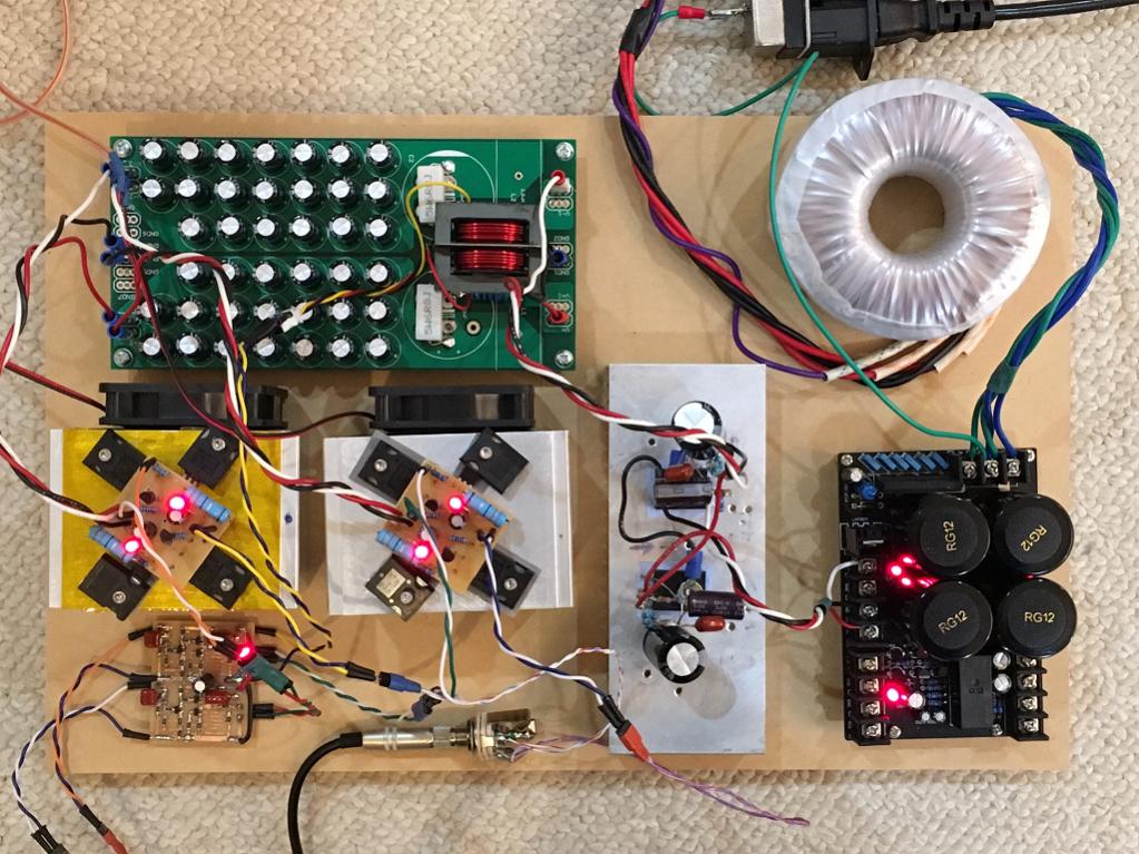
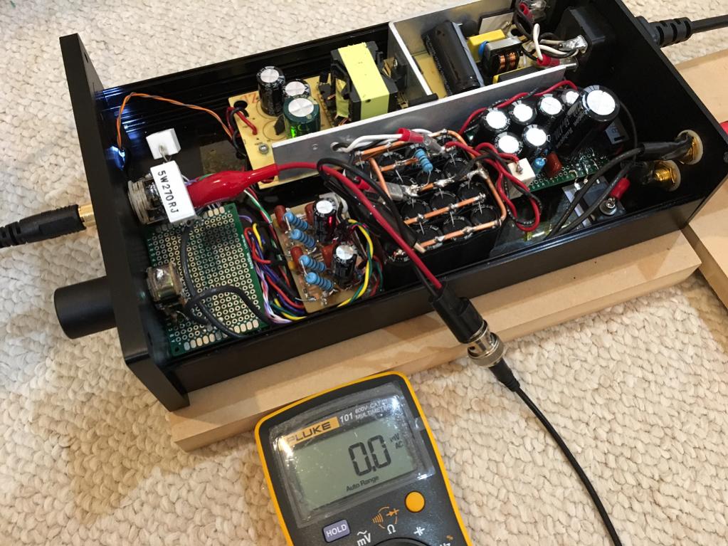
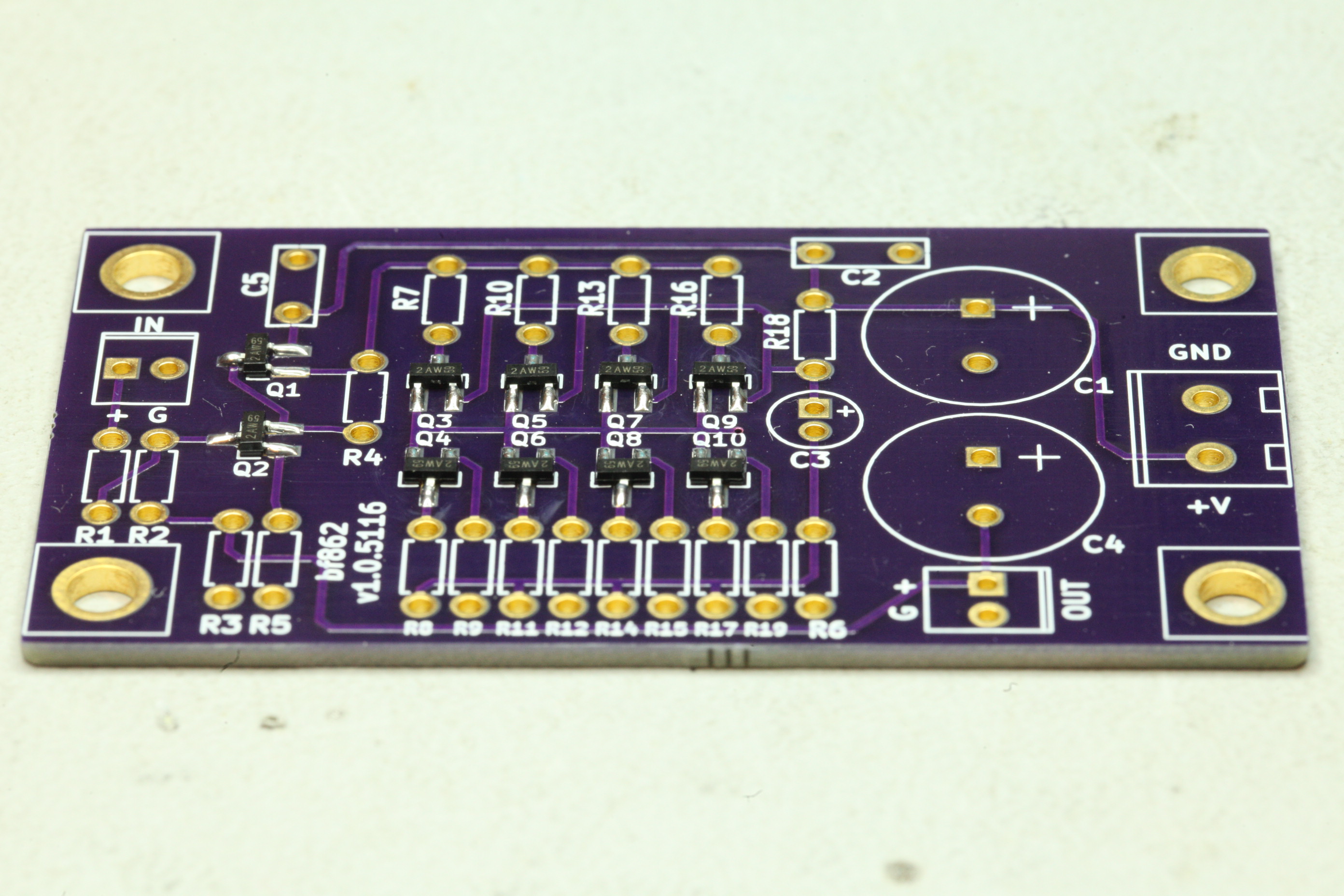
Nice PCB! You had that made at board shop in China?
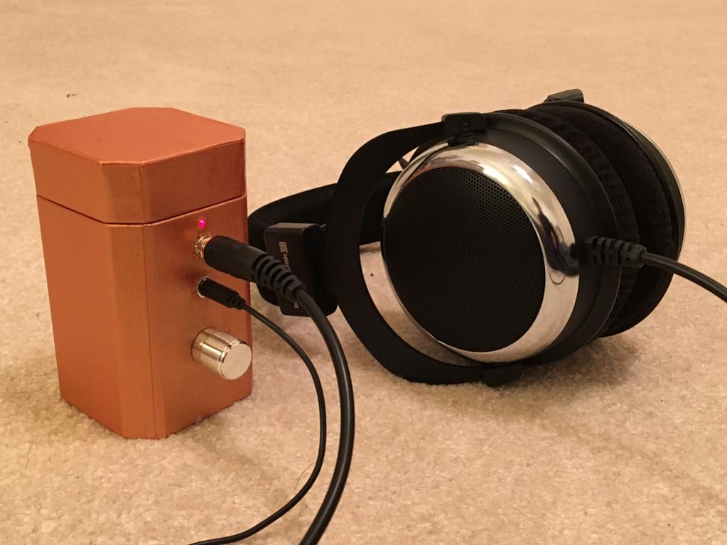
I just boxed up my 2 JFET amp:
Last edited:
Yes, I changed to 33R to get about 13mA current though ea leg. At 1R, it was basically too much current (saturated).
I'm just curious. What was voltage across (or current through) the drain resistor prior to your change? Do you remember?
Nice build. Packaging is historically where I start to lose interest.
The boards are from OSH Park. You get 3 copies per order. So I build up mono boards, small size keeps cost down. I've been using them exclusively for over 4 years, they have never fouled up an order. Seriously high quality boards, about 2 weeks (consistent) from upload to mailbox. And... they are made onshore, in the US.
I think I was getting like 23mA to 25mA per leg with the 1R. I heard you want it at 2/3rds if Idss for best operation.
What did 3 of those boards cost from OSH?
I think I was getting like 23mA to 25mA per leg with the 1R. I heard you want it at 2/3rds if Idss for best operation.
What did 3 of those boards cost from OSH?
Thank you. It sounds like something I'll want to change also, to reduce heat.
OSH Park has fixed price of $5 per square inch. That sounds expensive until you consider that you get three boards. The boards in the photo were approx 2.6" x 1.4" total cost $18.95.
In your as-built model, you changed R11a, R11b, R11c, and R11d from 1R to 33R. Was this a model-only change, or did you change this to reduce dissipation through the FETs? I've just started soldering parts on my board, and want to keep abreast of changes me by others and why. Why make the same mistake twice?
How is your amp build coming along? You should have sound by now.
- Home
- Amplifiers
- Headphone Systems
- BF862 based SE Class A Headamp without the HEAT