Is this the only effect the fins have, or do they also have a loading effect as mentioned earlier (can't remember who said this)?The fins do have an effect of spreading the high frequencies over 8KHz as Yuichi said in his article. Without the fins the size of the driver limits the upper frequency where there will be faster rolloff moving off axis.
Would it be beneficial to remove/leave the fins out if one were to use a separate tweeter horn above 8khz? I see @docali mentions in his post above that the fins are not phase coherent. Do the fins have a negative impact on lower frequencies?

That's the one I use. The correct designation should be A-320FL, as the design parameters are Fc = 320Hz and T=0.6.There is a version of the A-290 without the fins, the A-290FL was designed to be used with a pair of vertically mounted TAD-1601 woofers.
🙂
Is this the only effect the fins have, or do they also have a loading effect as mentioned earlier (can't remember who said this)?
Would it be beneficial to remove/leave the fins out if one were to use a separate tweeter horn above 8khz? I see @docali mentions in his post above that the fins are not phase coherent. Do the fins have a negative impact on lower frequencies?
The fins simply do not have the same path length for a flat wavefront. The design implies an acoustic point source what is not true.
Besides this, the fins are essential for proper loading! Look at original blue prints where each channel is a hyperbolic horn until they combine at fin end.
My own worksheets for traditional fin horns have another approach which is maybe easier to understand. Start with a conical horn with for example 80 degree opening angle. The origin ist still a point where the two side walls intersect in the negative. The throat diameter determines the distance from origin. At throat the arc crosses both outer throat walls building S_0 (surface are at throat). That's exactly the common approach. Then make the radius larger and draw the corresponding arc in the conical horn. Then calculate the construction wave front S_z. For the first cm S_z is obviously too large for hyperbolic expansion. What I do now is simply adding material on the arc evenly distributed. This give the fins. Then there will be exactly one z value where the conical horns S_z is equal to the hyperbolic formula. This is the fin end. From here on you can expand the vertical and the horizontal variables to preserve the hyperbolic S_z or even expand slightly faster if more flare is needed.
If I interpret the frequency plots in the paper correctly, the JBL 2441 has a more even response on the finless Yuichi than TAD 4001.There is a version of the A-290 without the fins, the A-290FL was designed to be used with a pair of vertically mounted TAD-1601 woofers.
But why exactly was this horn without fins developed when the purpose is still to use it as part of a two way system all the way to 20khz?
The documents I provided come directly from the old Yuichi geocities website so the A-290FL designation started with Yuichi himself.That's the one I use. The correct designation should be A-320FL, as the design parameters are Fc = 320Hz and T=0.6
This is the currently 3rd party hosted version of the site. Support for the A-290, A-290S and A-480 will be found here:
https://www.araihorn.com/p/horn-design.html
For the full collection of published designs, the original is available on archive.org AKA the wayback machine here:
https://web.archive.org/web/20190330060704/http://www.geocities.jp/arai401204/
Marco, do you have information specific to the A-320FL as I am unable to find any references to it, and it is not in my own library. (Edit: Siberia mentioned Yuichi changed it in the 2015 book I do not have unfortunately.)
Last edited:
It would be better if the vanes don't have to force compliance.. this would create disturbances.The fins do have an effect of spreading the high frequencies over 8KHz as Yuichi said in his article.
Shown trying to process a plane wave..
Compare this to feeding the vanes more cleanly to begin with.
The documents I provided come directly from the Yuichi website so the A-290FL designation started with Yuichi himself.
Yuichi has renamed it as A-320-FL in the book edition that was published in 2015. It's the same horn.
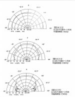
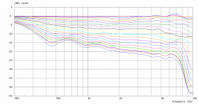
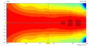
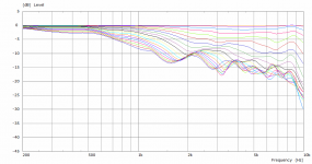
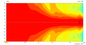
It's intended for large venues. Hence the comment "Therefore, the listener position is better to be located in far field such as 6m or 7m." A slight rise above 10K balances out with transmission space and narrowed directivity. Attaching directivity for the curious.If I interpret the frequency plots in the paper correctly, the JBL 2441 has a more even response on the finless Yuichi than TAD 4001.
But why exactly was this horn without fins developed when the purpose is still to use it as part of a two way system all the way to 20khz?
Attachments
The vanes are in the middle of the throat, the radiation pattern is not constrained by the vanes, but by the inner walls of the horn itself? (The geometry between the sidewalls and the adjacent vane is the same until the wave passes the tip of the vanes was what I understood.)The vanes should not be forcing compliance.. if there is a difference when they are used, they would create disturbances.
View attachment 1147423
Compare this to feeding the vanes more cleanly to begin with.
View attachment 1147424
This may not necessarily be a problem below a certain frequency, or within other limits of audibility. Seeing a problem displayed on a screen doesn't determine this despite how it may look, but it does point us in certain directions.
Yes, it won't be constrained by the vanes if the wavefront presents itself that way to begin with and travels normal to them. For example, in the second screenshot, waves in the "lanes" are travelling side by side and they meet up at the end thus avoiding disturbances. When disturbances occur away from the source, they can't be reasonably reconstructed, and they are called higher order modes.
Yes, it won't be constrained by the vanes if the wavefront presents itself that way to begin with and travels normal to them. For example, in the second screenshot, waves in the "lanes" are travelling side by side and they meet up at the end thus avoiding disturbances. When disturbances occur away from the source, they can't be reasonably reconstructed, and they are called higher order modes.
Last edited:
I could have made the same point using straight lines instead of shaped vanes, so we'd need to be specific if it's to make a difference. However yes, the walls do resemble the vanes along the same axial travel, IIRC.(The geometry between the sidewalls and the adjacent vane is the same until the wave passes the tip of the vanes was what I understood.)
From Yuichi.

Also he mentions the A-290 is intended for listening at a minimum distance of about 2 meters, I am at 4 meters. I can confirm that at 2 meters they sound fine. My very vague recollection is the A-290 was intended to provide improved near field performance as compared to the TH-4001. I can no longer find this reference.
Also he mentions the A-290 is intended for listening at a minimum distance of about 2 meters, I am at 4 meters. I can confirm that at 2 meters they sound fine. My very vague recollection is the A-290 was intended to provide improved near field performance as compared to the TH-4001. I can no longer find this reference.
Last edited:
Audibility matters. It's probably as important to understand things so we don't read too much into them as it is the other way around. For example..
On re-reading this it sounds like it might have been a regular throwaway comment.. however the first thing that came to my mind was that there was a pressure differential either side of the vane due to mismatched wavefronts. I don't know which was intended.Yuichi said:Just thin separators will creates some problems. Therefore the fins has to be reasonably robust.
I think this was part of Pano's confusion. The fins in the A290 are necessary for it to be Hyperbolic, if they were removed and just the basic horn shell left as is the overall response would be quite different. The side wall forms half of the cell on the left and right with the fins forming the rest. This can be seen like a multicell or a phase plug. The original A290 is not perfect in this regard the fins can be modified for an improvement.Is this the only effect the fins have, or do they also have a loading effect as mentioned earlier (can't remember who said this)?
Would it be beneficial to remove/leave the fins out if one were to use a separate tweeter horn above 8khz? I see @docali mentions in his post above that the fins are not phase coherent. Do the fins have a negative impact on lower frequencies?
If a horn with no fins is made with the same Hyperbolic T 0.7, the size of the throat dictates the point where the high frequencies begin to beam more strongly. It still happens far off axis with the fins but the blue null seen in the graphs below would intrude much more without the fins
Here is an example of one of docali's designs that I really like, a finned horn of similar size and look to the A290 but more refined and controlled..
Attachments
Very interesting, is this a publically available design @docali ?Here is an example of one of docali's designs that I really like, a finned horn of similar size and look to the A290 but more refined and controlled..
@Lament
This was a collaboration with DonVK and fluid. My task was to provide the worksheet programming and math implementation. I lost a little the overview as we have tested a lot of things for several months. For me it would be ok to publish this single File mk3b2 if Don and Duncan agree. iirc fluids size restrictions resulted in a smaller horn compared to the A290. cut-off was in the range 320-350 Hz. The design surpassed the original Yuichi and I believe because of two reasons. The used half fin method for outer fins (followings Kolbrek/Dunker) and optimized flares. We also created a better adapter for a bit wave front shaping.
This was a collaboration with DonVK and fluid. My task was to provide the worksheet programming and math implementation. I lost a little the overview as we have tested a lot of things for several months. For me it would be ok to publish this single File mk3b2 if Don and Duncan agree. iirc fluids size restrictions resulted in a smaller horn compared to the A290. cut-off was in the range 320-350 Hz. The design surpassed the original Yuichi and I believe because of two reasons. The used half fin method for outer fins (followings Kolbrek/Dunker) and optimized flares. We also created a better adapter for a bit wave front shaping.
What I forgot as it is some sort of funny. The mk3b2 version was from an early stage and I pushed a lot of new ideas in the queue but I could not really convince Duncan to abandon the mk3b2. ;-) I have to admit that it is a really good candidate for a 2in fin horn.
Could you please arrange the fins in away that the outer rotational angle is half of the inner for the flat wave front? So, if you have 80 degree in total the inner channel angle is 40 and both outer channels have 20.The vanes would be better not forcing compliance.. if there is a difference when they are used, they would create disturbances.
View attachment 1147423
Compare this to feeding the vanes more cleanly to begin with.
View attachment 1147424
It would be nice if you could describe the workflow how configure and feed the ripple tank simulator.
- Home
- Loudspeakers
- Multi-Way
- Beyond the Ariel