220k from plate of 6550'kt88 to plate of 6sn7 will lower plate resistance of the output tube some more..
@TonyTecson
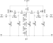
I'm just trying to gain absolute clarity.
Is this (below) what you were suggesting?
Last edited:
Not much point in using Schade fbk with lowish gain triodes, IMHO. The benefit from the local fbk on the output stage is limited by the increased work the driver has to do (in other words small amount of fbk can applied). Instead a higher sensitivity pentode (it could also be a pentode with modest gm but used at lower g2 voltage than plate voltage, hence higher gain) gives more benefits. The triode with local fbk is surely some improvement in comparison to GRND feedback but nothing comparable to pentode + local fbk that also has significantly higher efficiency. Once local fbk is applied (be it Schade or cathode fbk) it behaves like a triode in ALL aspects (sound included) except one gets more power with lower distortion.

the 220k 3 watt metal film resistor is done on both plates of the 6550..@TonyTecson
I'm just trying to gain absolute clarity.
Is this (below) what you were suggesting?
View attachment 1192083
very easy to implement, and if you do this, keep it in ultra-linear mode too..
running the kt88/6550 in triode, you should be able to run without the gnfb,
but i seen no harm in trying it in triode too, all the more reason to go without gnfb..
another mod is to use separate cathode bias resistors per 6550 tube, 470ohm 5watt metal film is what i use...
the Japanese have been doing it since the 60s, that is where i saw it first...Not much point in using Schade fbk with lowish gain triodes, IMHO. The benefit from the local fbk on the output stage is limited by the increased work the driver has to do (in other words small amount of fbk can applied). Instead a higher sensitivity pentode (it could also be a pentode with modest gm but used at lower g2 voltage than plate voltage, hence higher gain) gives more benefits. The triode with local fbk is surely some improvement in comparison to GRND feedback but nothing comparable to pentode + local fbk that also has significantly higher efficiency. Once local fbk is applied (be it Schade or cathode fbk) it behaves like a triode in ALL aspects (sound included) except one gets more power with lower distortion.
that is why running the 6n8 with more plate current and lower plate load resistors can keep up with the demands of the output tubes, all within reason, that is never exceed tube pate dissipation ratings of say 6 watts or 3 watts per plate, but i am sure it will never come to this...
in my 6550 build i opted to use mosfets G2 regulators for the screens in a pure pentode mode, i would say i like the sound very much, i am a big fan of pentodes, the client was happy too...
very easy to implement, and if you do this, keep it in ultra-linear mode too..
It appears from these comments that SCHADE FEEDBACK is best deployed in an UL amp.
My amp has NOT run in UL for years.
As shown in the above schematic, the UL switches were removed long ago and the amp is TRIODE ONLY.
It won’t be returning to UL.
I prefer to have the amp optimised for ONE mode of operation - and TRIODE is it.
the other option would be, G2 regulators like what i have....this is for TV power tubes where G2 is in the 150vdc ranges...but understand that your output transformers will always be the bottleneck
in any case...
in any case...
Attachments
Last edited:
TRIODE OPERATION ONLY
When I reduced R6 down to the new value of 10K, I noticed that an entirely new hardness and dryness has crept into the tops - making it difficult to enjoy the positive attributes that the R6 change delivered, which is improved dynamics and slightly tighter bass.
A question to more experienced tube amp tuners:
Will reducing the value of R9 and R10 to (say) 22K help restore some sweetness to the tops?
Or will I need to revert back to the higher value R6?
It seems to me that Schade negative feedback and a triode driver tube works best if the triode's cathode resistor is somewhat large, and does Not have a bypass cap. That makes the driver triode's plate impedance, rp, fairly high. That is good for Schade feedback, which is why a pentode driver is often used instead of a triode driver.
All well and good for Single Ended amplifiers.
But this amplifier is Push Pull, and the driver cathodes are tied directly to each other, that keeps both triode's plate impedance, rp, fairly low, no matter how high the common cathode resistor is (similar to an LTP).
That may Not be as good when using Schade negative feedback in push pull; versus the success of single ended Schade negative feedback.
Post # 241:
In your case, the driver stage and the phase splitter stage are one and the same.
The input triodes are not a phase splitter.
It also seems to me, that the more successful Schade negative feedback single ended amplifiers use output stages that are either pentode, beam power tubes in their native pentode or beam power modes, or at least are in Ultra Linear mode. I see less successful ones that are in Triode wired mode. Just something about Schade negative feedback that seems to like higher gain output stages.
For push pull instead of single ended, who knows, but I bet the same principle applies.
I do not know if the hardness and dryness you are hearing is because of any of the above observations.
Just my opinions and especially my curiosity.
Have fun and Good listening!
Last edited:
@6A3sUMMER The higher rp in triode mode still doesn't change its gain so the amount of work the driver has to do doesn't change. Having higher gain, less voltage needs to be fed back for the the same amount of feedback. In turns this means less voltage drive is required. The difference can be rather big. For example if the normal driving voltage is 45V and 6 dBs feedback are desired the driver needs to swing 90V. If the output tube is biased in pentode more or less around 24V, for the same amount of fbk only 48V drive are needed. Quite a difference! The pentode with fbk only needs approx the same drive of the triode without fbk.....
As suggested by @TonyTecson, you could add his regulator. An excellent working point for the KT88 would be: plate voltage in the 400-450V range and g2 voltage around 250V. This gives high gain and high efficiency. In SE mode, I can get 20W (that can only be class A by definition) from a single KT88 with 420V plate voltage and 250V on g2 with low distortion even without feedback. It's a rather optimized working point and results in more or less the scenario I am have described above in reply to @6A3sUMMER.....
It is best deployed in pentode/tetrode mode and I agree that one cannot have all operation modes optimized.It appears from these comments that SCHADE FEEDBACK is best deployed in an UL amp.
My amp has NOT run in UL for years.
As shown in the above schematic, the UL switches were removed long ago and the amp is TRIODE ONLY.
It won’t be returning to UL.
I prefer to have the amp optimised for ONE mode of operation - and TRIODE is it.
As suggested by @TonyTecson, you could add his regulator. An excellent working point for the KT88 would be: plate voltage in the 400-450V range and g2 voltage around 250V. This gives high gain and high efficiency. In SE mode, I can get 20W (that can only be class A by definition) from a single KT88 with 420V plate voltage and 250V on g2 with low distortion even without feedback. It's a rather optimized working point and results in more or less the scenario I am have described above in reply to @6A3sUMMER.....
I do not know if the hardness and dryness you are hearing is because of that.
The (new) hardness and dryness in the sound ONLY emerged following my reducing the (second) 6SN7 shared cathode resistor R6 from 18K, to 10K.
[Note: I previously believed R6 was set at 15K and was surprised to recently remove the resistor and find it was 18K...]
I am now experimenting with R9 and R10 loading resistors, reducing them from 30K, to 23K - for an initial test. I am hoping the (new) hardness and dryness in the sound will disappear.
Thanks for your SCHADE FB insights too, 6A3sUMMER.
I have since discarded the SCHADE FB idea, for my triode ONLY amp.
As suggested by @TonyTecson, you could add his regulator. An excellent working point for the KT88 would be: plate voltage in the 400-450V range and g2 voltage around 250V. This gives high gain and high efficiency. In SE mode, I can get 20W (that can only be class A by definition) from a single KT88 with 420V plate voltage and 250V on g2 with low distortion even without feedback. It's a rather optimized working point and results in more or less the scenario I am have described above in reply to @6A3sUMMER.....
Thanks 45.
If my forthcoming tests with reduced value load resistors don't solve my present hardness and dryness problems, I will give @TonyTecson 's G2 REGULATION circuit my closest consideration.
[Thanks Tony]
if you regulate G2, you will have to regulate g1 bias too...
but in my case, i stick to cathode resistor bias too....
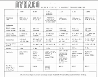
still, I would remind you that your output transformer could be your bottleneck too..
and if you look closely to the table below, the opt powers are not the same at the 30hz and 15khz, compared to 20hz to 20khz.
Dynaco outputs catalog: http://knob.planet.ee/kirjandus/books/Dynaco_Transformers.pdf
but in my case, i stick to cathode resistor bias too....
still, I would remind you that your output transformer could be your bottleneck too..
and if you look closely to the table below, the opt powers are not the same at the 30hz and 15khz, compared to 20hz to 20khz.
Dynaco outputs catalog: http://knob.planet.ee/kirjandus/books/Dynaco_Transformers.pdf
Attachments
Last edited:
45,
I think you are correct.
It is late, and my brain is toast.
But here goes . . .
For Schade negative feedback, the driver plate impedance, rp, is in parallel with the driver plate load . . .
That forms the Ri in the op-amp formula related to Ri and Rf.
Right?
And here goes again . . .
The gain (open loop) of a pentode or beam power tube is Transconductance, Gm x Primary impedance (whole primary impedance for SE; and in class A push pull is 1/2 of the whole primary impedance).
Right?
Whereas again . . .
The gain (open loop) of a triode wired pentode or triode wired beam power tube is u x (primary impedance RL / (primary impedance RL + plate impedance rp)).
(whole primary impedance for SE; and in class A push pull is 1/2 of the whole primary impedance, with rp / 2).
Right?
I hope I got it right.
I am distracted by my stereo playing Shirley Horn, but do not blame her.
Are we talking about Regulated Screen voltages . . .
But at the same time talking about using Triode wired pentodes / triode wired beam power tubes?
Those are two completely different output stages, and never the twain shall meet.
Triode wired, intrinsic low(er) output impedance with no other negative feedback.
Has often been used successfully.
Real damping factor.
Pentode / beam power operation, intrinsic high(er) output impedance with no other feedback.
Unreasonably low damping factor.
Usually needs some kind of negative feedback to make it successful.
All generalizations have exceptions.
@TonyTecson
I'm just trying to gain absolute clarity.
Is this (below) what you were suggesting?
View attachment 1192083
the Schmidt phase spliter is complex, you are interested in the ultimate version developed on the Hitone H300.
note the balance potentiometer and the small 1.8pF capacitor between the plate and the grid of the upper triode, it is important.
When I bought a wrecked H300, the person who had massacred this amp had set up a 1.8nF and the sound was really muffled, I took a while to find and as soon as I restored the 1.8 pF, the sound became what it should be, then I played with a variable capacitor to establish that the optimum range was between 1.8 and 4 pF.
This phase spliter is very complex and very difficult to adjust if it is not perfectly implemented.
I don't have the skills to help you, I'm just sharing my experience, but many competent people here can do it from this diagram.
Adjusting and listening - and adjusting again and listening again...
This has been a very interesting exercise, for my learning!
Tonight, I reduced the load resistors R9 and R10 from 30K, down to 23K. The overall dynamics improved further, and the hardness and dryness in the sound has started to disappear; but not entirely.
The good news is that whilst the tube measurements changed as a result, all tubes are still well within maximum operational parameters.
Obviously, there are mutually impacting relationships between the values of R6, R9 and R10 - and the resulting sound; relationships that I am only just beginning to understand.
I am allowing the new R9 and R10 23K resistors to burn-in for a few more hours overnight - making best efforts to ensure that I don't make an overly hasty evaluation, as I have previously - to be sure I have heard all that the new values can offer.
Tomorrow - if I still detect the hardness and dryness - I will experiment further by reducing R9 and R10 to just 20K. After checking the measurements to ensure the tubes are happy, I will give that a good long listen.
If the hardness and dryness still does not completely disappear, I will slowly increase the value of R6 again - perhaps to around 12K as a next step - in the hopes that some smidgen of warmth is restored to the sound. Let's see.
I will report.
i am not a fan of using the ears to measure things, a scope, some square wave testing at some points can reveal more than just listening alone, if you persist, you will never see the end of it...
i still think that your output transformer is limiting your perceived performance....
i once got hold of a pp kt88 from Cayin, one opt was burned out, upun inspection i found that the amp used an opt meant for the el84, i thought it was a ripoff....
i still think that your output transformer is limiting your perceived performance....
i once got hold of a pp kt88 from Cayin, one opt was burned out, upun inspection i found that the amp used an opt meant for the el84, i thought it was a ripoff....
I hope I got it right.
I am distracted by my stereo playing Shirley Horn, but do not blame her.
😆😆😆
i am not a fan of using the ears to measure things, a scope, some square wave testing at some points can reveal more than just listening alone, if you persist, you will never see the end of it...
I understand your perspective.
Your 4 x 6SN7 /ZERO GNFB suggestion was a revelation to our ears - but I bet it measures worse than the full GNFB factory configuration that sounded less good.
It is our ears that have to live with it, so three pairs of ears have the final say around our way. 😉
- Home
- Amplifiers
- Tubes / Valves
- Bewitch KT88