Thanks for you help ThorstenL.
I run the 12LT and FT17H from a trends t10.1 amp and the subs will be run from one sub amp each.
Is the hi level still the way to go?
I run the 12LT and FT17H from a trends t10.1 amp and the subs will be run from one sub amp each.
Is the hi level still the way to go?
I'm still messing around with these. Today I learned that the rise in Fs was due to colder temps in my basement workshop during the winter. I put the driver by the woodstove for a few hours and my Fs dropped to 57 Hz. This is about what I started with when I measured last fall. This new reading is for the whizzerless driver.
Thinking again about adding a coaxial tweeter.
Thinking again about adding a coaxial tweeter.
JRKO, i just looked at your amp and think this is the way you should wire things. First, i would use just one amp. I would build a box for it and allow it to stand on it's own. Run wire from the T-amp to the main speakers just like you are now. Also run wire from the same terminals of the T-amp to the sub amp. Connect into the push terminals 'From Amp' (filling the four push terminals on top). Then from the wires coming out the rear of the sub amp connect the Positive from BOTH Beta 15s to the red and Negative from BOTH Beta 15s to the black. This will result in a 4 ohm load.
That's what i would do.
Zilla
That's what i would do.
Zilla
Hi,
It is at least very much worth trying...
Ciao T
I run the 12LT and FT17H from a trends t10.1 amp and the subs will be run from one sub amp each.
Is the hi level still the way to go?
It is at least very much worth trying...
Ciao T
JRKO, i just looked at your amp and think this is the way you should wire things. First, i would use just one amp. I would build a box for it and allow it to stand on it's own. Run wire from the T-amp to the main speakers just like you are now. Also run wire from the same terminals of the T-amp to the sub amp. Connect into the push terminals 'From Amp' (filling the four push terminals on top). Then from the wires coming out the rear of the sub amp connect the Positive from BOTH Beta 15s to the red and Negative from BOTH Beta 15s to the black. This will result in a 4 ohm load.
That's what i would do.
Zilla
I'm gonna run the subs singly of each amp as I'll be crossing over between 150-200htz which I believe is still quite directional and so a stereo pair should 🙂confused🙂 be best.....i hope. That and I got 2 of the amps! Might add another 2 15's at some point just for kicks 😀


Last edited:
Enjoy the building process. Be careful cutting and sanding. Cut off the dustcap of the 12lta if you have not already. Much more enjoyable and natural sounding. I have not had the urge to even add the 98 cent tweak... You will love it! Keep us posted on your progress.
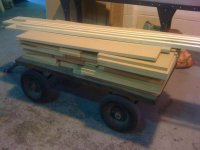
Just popped home for dinner. I'm assembling them at a friends who has a huge garage. Going back after to complete the first build. They will come home unpainted.
Bass units are 55 deep, 70 wide and 85 tall. These will be put together for fit and then dismantled for final fix at home to make transporting them easier.
I got some 10 thick x 25 wide pine for the tweeters. Should make them nice and snug
Bass units are 55 deep, 70 wide and 85 tall. These will be put together for fit and then dismantled for final fix at home to make transporting them easier.
I got some 10 thick x 25 wide pine for the tweeters. Should make them nice and snug
>>> 55 deep, 70 wide and 85 tall.
You went smaller than 11cf. Still plenty big!
To give you an idea of the size I'm 6ft 4 and the cabinets are on some 22cm high blocks.
Spot the deliberate mistake. I cut the hole for the 12lt way off centre 🙄 - another sheet tomorrow will sort that out 😱
Attachments

FWIW, when baffles get wide enough to have a golden or acoustic ratio offset, which yours appear to do, it's a good plan to do it to average out its eigenmodes somewhat......... That, or put appropriate density open cell foam 'bumpers' along its edges if the baffles aren't ~ hemispherical in shape.
GM
GM
Correct, if you use one of the acceptable ratios such as the golden 0.618:1.00. I can never remember any of the others, I'll have to look them up.
GM
GM
That, or put appropriate density open cell foam 'bumpers' along its edges if the baffles aren't ~ hemispherical in shape.
GM
Thanks for you interest and comments GM. Could you enlighten me about the 'bumpers' please? Not sure what these are or how they work. Thanks in advance
........acceptable ratios such as the golden 0.618:1.00.
Found a few room ratios and I imagine that more can be found Googling, so ideally you would use all three for a driver offset, but our hearing is heavily weighted towards the horizontal, so just one of the two ratios works good enough:
1: 1.17: 1.47
1: 1.45: 2.10
1: 1.28: 1.54
1: 1.25: 1.60
1: 1.26: 1.41
Or, you can generate your own:
nx : 2^(1/3)ny : 2^(2/3)nz
where nx,ny,nz are integers
GM
Could you enlighten me about the 'bumpers' please?
You're welcome!
Properly designed 'bumpers' absorb/dissipate energy, so to attenuate a panel's acoustically generated eigenmodes (standing waves) some sort of open cell foam or similar panel edge cap is required (ideally on all edges) if not rounded over enough. Note that it doesn't need to be on the edge, just relatively near it: http://www.nhthifi.com/site/images/33lg.jpg
That, or cover all the baffle around the driver with it and ideally the whole cab.
In earlier times, a well designed speaker would have a grill designed to do this as well as smooth out any excessive 'sharpness'/whatever to its presentation, especially in the (super) tweeter BW in an 'acoustic solutions to acoustic problems' design mentality, but over time and with increasing market competition, manufacturers were forced into containing cost and individualizing a product's 'look' as much as practical, so drivers today tend to be much more cosmetically appealing, using electrical filters and doping/whatever its diaphragms as required to do this since both are cheap in quantity and designing complex XO's is relatively quick/easy nowadays.
So, what density foam/whatever is required? Unfortunately, without the physical properties of each type of material and the math + skills to figure it out it can only be found empirically if there's no proven existing design data that might work for your app. Asking Owens-Corning seems as good a place as any to start since they have many decades of experience dealing with all manner of acoustic transmission attenuation. Ditto whichever foam manufacturer has enough experience or at least willing to work it out for you.
GM
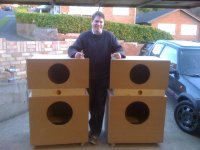
I probably missed it but what's going in those cabs? Every time I look at my 126e's in all their glory, big cabs with big woofers are always calling me. Good work and looks fun.
I probably missed it but what's going in those cabs? Every time I look at my 126e's in all their glory, big cabs with big woofers are always calling me. Good work and looks fun.
Eminence 12LT full rangers in the 'smaller' top cabinet. Fostex FT17H in the middle solid block of Pine and Eminence Beta 15 inchers in the bottom
I'm wiring them up tomorrow - cant wait 😀😀😀😀😀😀😀
- Status
- Not open for further replies.
- Home
- Loudspeakers
- Full Range
- Beta 12LTA in a 3cf box - port size