I'm also 41 so i do enjoy a bit more bass and highs...
All the values should be different for other tape heads and should be tweaked accordingly .
You are on an empirical path to trim your equipment output match your taste (preference).
That’s perfectly all right for you and anyone else around.
At the same time, this makes you the only one to be able to answer your questions 🙂
I simply can't make my mind which RC network to choose best with the R1
George
Indeed... usually i can get it right only through countless series of comparative listening but an oscilloscope ca make the difference.I made the feedback resistor 60k(68k//1meg//1meg) though today...You are on an empirical path to trim your equipment output match your taste (preference).
That’s perfectly all right for you and anyone else around.
At the same time, this makes you the only one to be able to answer your questions 🙂
George
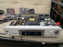
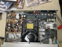
As somebody suggested me with justified irony that the best cd-player mod would be a better cd player...I just bought a Sony DVP725 dvd-player and i'm amazed of the components quality...Unfortunately it's headphones amp is a njm4580 in noniverting topology and the dac are vout types that sounds completely uninvolving.No slew rate, no power, no nothing...At least i have good op-amps and a state of the art power supply now.
Attachments


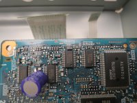
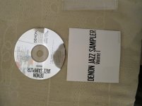
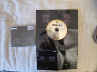
Denon Test Disc-1986
Attachments


Last edited:
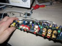
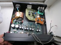
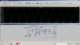
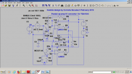
This would be the last mod i did around the i/v converter for the tda1543.I wanted to make the i/v output even lower so i made the feedback resistor 500 ohms, paralleled both sections of each op-amp .
Although, from the beginning i should have doubled the integrating capacitor's value when i halved the feedback resistor i found that the sound is cleaner with half of the optimal value.
For years i had to listen to all sorts of myths around lm833 , like this should be an inferior part and such.Well...IT'S NOT! You just need to give it the right food.I couldn't hope for a better sound than this old player could give me to be honest.
I'm thinking of cascoding the i/v input as to make a lower capacitive input , but i don't really feel a need for smth like this.
Right now i'm building a new box with my new "effect" and hopefully i'd be able to try it on better cd-players as they are.I'm using spare parts from 3 cd players , one dvd player and an audio class d amplifier of which i had the box.
As i can only hear up to 14 or 15 khz...depending on the test...i don't really care of higher end equipment.I'm in my 40's now and most of the audiophile guys i know are in their 50's or 60's...and can't even hear the 12khz test , so I believe that my garbage player is high end for more people than you'd believe.
Attachments
-
 IMG_5322.jpg661.7 KB · Views: 105
 -
 IMG_5326.jpg1 MB · Views: 112
 -
 IMG_5327.jpg994.8 KB · Views: 142
 -
 IMG_5330.jpg781.7 KB · Views: 104
 -
 IMG_5333.jpg638.9 KB · Views: 90
 -
 IMG_5324.jpg792.6 KB · Views: 97
 -
 IMG_5292.jpg991.2 KB · Views: 96
 -
 IMG_5336.jpg1,009.6 KB · Views: 85
 -
 IMG_5337.jpg768.5 KB · Views: 92
 -
 IMG_5340.jpg643.5 KB · Views: 103
Last edited:
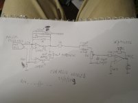
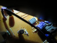
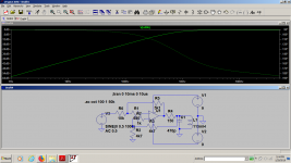
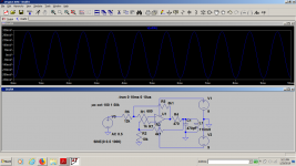
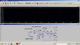
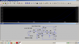
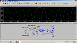
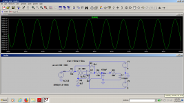
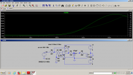
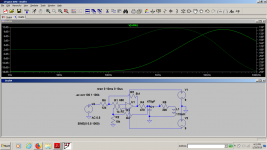
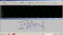
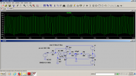
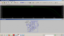
Because I'm attempting to make a stand alone box just for the digital garbage masking effect , and because i felt I wanna understand more on what you can do with the cheap njm4556, i started to sim some drivers for the rec head used by Yamaha in their kx-930 and kx1200 cassette recorders for the rec head with just their universal op-amp model, but i also wanted to sim it with my headphones impedance just for fun.I don't really know how to sim my headphones load though...I just measured their inductance and resistance with a simple meter and i put those values in series...I will use their simple inverted topology for the headphones section.
You can do your own investigations changing the value of all components and op-amp models, even your tapeheads or headphones models. As i have no idea how to calculate gain when you have both positive and negative feedback in an op-amp i used the mighty LtSpice to help me.
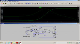
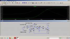
You have a glimpse of the final device in the last photo and the final sim of the yamaha kx 930gain , less than one obviously but that is only because of the 270 ohms output resistor .If i use 150 ohms resistor the gain is suddenly 2X instead of 0.3X .
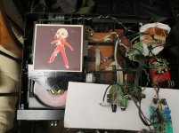
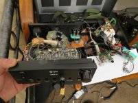
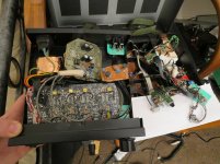
Each device was carefully prepared .I still have no means for measuring my toy, but i fully trust my ears and anyway...this device is made for me to accept the sound of an old cd player which otherwise isn't really a great one....
You can do your own investigations changing the value of all components and op-amp models, even your tapeheads or headphones models. As i have no idea how to calculate gain when you have both positive and negative feedback in an op-amp i used the mighty LtSpice to help me.
You have a glimpse of the final device in the last photo and the final sim of the yamaha kx 930gain , less than one obviously but that is only because of the 270 ohms output resistor .If i use 150 ohms resistor the gain is suddenly 2X instead of 0.3X .
Each device was carefully prepared .I still have no means for measuring my toy, but i fully trust my ears and anyway...this device is made for me to accept the sound of an old cd player which otherwise isn't really a great one....
Attachments
-
 yamaha930sym.png62.8 KB · Views: 91
 -
 yamahaliketapehead.png62.2 KB · Views: 93
 -
 IMG_5382.jpg825.2 KB · Views: 101
 -
 IMG_5383.jpg995.5 KB · Views: 96
 -
 IMG_5384.jpg519.7 KB · Views: 82
 -
 IMG_5385.jpg602.9 KB · Views: 86
 -
 IMG_5388.jpg812.1 KB · Views: 90
 -
 yamahakx930-symf.png64.1 KB · Views: 96
 -
 YAMAHA930h.png63.7 KB · Views: 82
 -
 YAMAHA-HEAD2.png61.8 KB · Views: 73
Last edited:
I wonder what's the meaning of all This...
Attachments
-
 Yamahahead3.png63.7 KB · Views: 75
 -
 yamahahead4.png65.4 KB · Views: 77
 -
 yamahahead5.png62.2 KB · Views: 77
 -
 yamahahead6.png61.3 KB · Views: 66
 -
 yamahahead13.png63 KB · Views: 72
 -
 yamahahead11.png60.9 KB · Views: 80
 -
 yamahahead10.png61.8 KB · Views: 63
 -
 yamahahead9.png63.4 KB · Views: 71
 -
 yamahahead8.png63.5 KB · Views: 73
 -
 yamahahead7.png61.9 KB · Views: 66
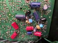
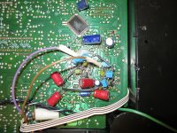
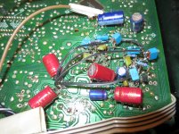
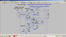
Paralleling the i/v sections of a double op-amp was the most stupid thing i did as the dc offset for lm833 led to one's output close to +rail in one op-amp and to -rail in the other, but the sound somehow became "better" whatever it might be with a double load on one op-amp(500 ohms), but less capacitance than it should be there.Actually this lm833 doesn't stop amazing me.I've tortured it in countless ways.
Last edited:
Now i finally solved the parallel I/V section problem and the sound is acceptable, but actually not better than the LM833 alone.I just used the components i had at hand to verify if it's possible to do it and it works really well.I might try a few different values for the caps here and there , but the topology is valid and applicable to other DAC's too.
Attachments
I finally made it!
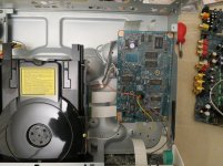
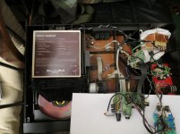
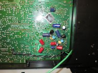
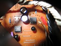
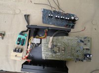
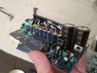
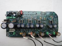
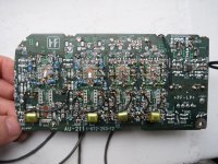
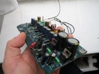
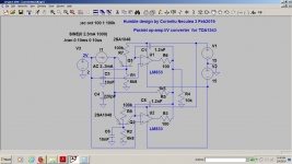
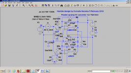
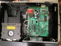
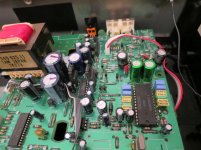
After a few weeks into trying some new ideas, i started to build a final I/V stage based on paralleling both sections of a lm833 op-amp so that I can drive easily some tough loads including some a passive filters .
I settled on two variations .One was used for higher gain to drive the headphones amplifier directly at double gain(1k5 feedback resistor) the other to drive the tape-head system that has it's own gain , (750 ohms feedback resistor).
The simulations are meaningless, they just helped me to find the right combination of passive components.
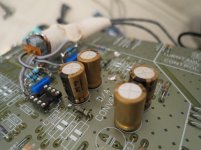
The capacitor values aren't really the best choice, i just had those values among my limited components stock...I should have used actually bigger capacitors for the resistor feedback values to have the right frequency content ,but no matter how many values i tried , i always liked the sound that came out with half the values Philips chose for this i/v converter attached to TDA1543 in cd610 mk2 setup.
I'd go with lower noise transistors, but i was actually lucky to find those 2sa1048 around(from an old Toshiba cd player actually).
The C4 capacitor is essential for the slew rate and high contents.I tried first 330pf in both configurations , then i settled on 130pf for a little bit more highs as I'm a bit deaf for my 40's.220pF would probably be the best value here.
Although some measurements might help , I'm absolutely sure that the right choice of the components values would actually be a matter of personal preference with such a setup.
Now i can swear for this I/V converter.
After a few weeks into trying some new ideas, i started to build a final I/V stage based on paralleling both sections of a lm833 op-amp so that I can drive easily some tough loads including some a passive filters .
I settled on two variations .One was used for higher gain to drive the headphones amplifier directly at double gain(1k5 feedback resistor) the other to drive the tape-head system that has it's own gain , (750 ohms feedback resistor).
The simulations are meaningless, they just helped me to find the right combination of passive components.
The capacitor values aren't really the best choice, i just had those values among my limited components stock...I should have used actually bigger capacitors for the resistor feedback values to have the right frequency content ,but no matter how many values i tried , i always liked the sound that came out with half the values Philips chose for this i/v converter attached to TDA1543 in cd610 mk2 setup.
I'd go with lower noise transistors, but i was actually lucky to find those 2sa1048 around(from an old Toshiba cd player actually).
The C4 capacitor is essential for the slew rate and high contents.I tried first 330pf in both configurations , then i settled on 130pf for a little bit more highs as I'm a bit deaf for my 40's.220pF would probably be the best value here.
Although some measurements might help , I'm absolutely sure that the right choice of the components values would actually be a matter of personal preference with such a setup.
Now i can swear for this I/V converter.
Attachments
I needed to listen again to the original sound give by the lm833 alone so i built a parallel circuit outside the cage that i could switch to .I also modified both circuits to the preferred value of passive components , finding that 100 ohms-1.5nF//1kohm is the most pleasing combination for me. I simply can't make my mind which circuit sounds better...the simple lm833/njm 2114 based op-amp or my ultra-complicated version. If i get very low noise transistors , the transistor front end version would allow me to choose among a variety of op-amps that wouldn't be suitable before . Comparing lm833 with njm2114 i found lm833 sounding a bit louder.In all honesty i can't find my circuit being superior to the original one, nor inferior, but it opened my mind on how i/v circuits work .
The tape-head device is still doing its job.
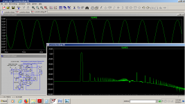
I tried some LC filter before the I/V stage as others suggested but i only get to raise the noise floor doing it .I can indeed make the sound a bit smoother by adding a clc filter before the op-amp, with a noise penalty.I will try more filtering options, but what i got for now it's good enough.
The tape-head device is still doing its job.
I tried some LC filter before the I/V stage as others suggested but i only get to raise the noise floor doing it .I can indeed make the sound a bit smoother by adding a clc filter before the op-amp, with a noise penalty.I will try more filtering options, but what i got for now it's good enough.
Attachments

Actually i could make my mind listening to both of them today and it was as expected.The transistor front end is a little bit noisier on high notes , but you can hardly hear the difference, while the lm833 alone (half of a dual op-amp on the same load) is a bit slower or mellow sounding on percussive notes.I asked a friend to listen the same toy and he came up to the same conclusion in just 15 minutes.To be honest they both sound well to me.It's just that this arrangement can be used with lower impedance loads and in higher number of paralleled devices for lower noise.
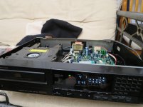
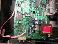
As i found a Sony CDP750 for free, i spent one night to prepare it for the i/v beast but first i wanted to use the same i/v stage configuration of Sony cdp 227 es as i listened to that player once and , although the chipset configuration is quite different, i could remember the sound i heard listening to a 227 es by simply using the same r-c values series with a 120ohm resistor on a dual njm2114...less bass , more mid-highs...but i Like the Bass! so I simply made the capacitor value a bit lower et voila, the base is back, just lost a bit of resolution in the highs department, where tda1541 was shining.Then i reintroduced the right capacitor value and ran the whole thing through my box effect that cuts the highs a bit so now it's more realistic.
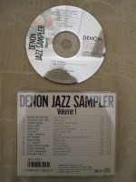
At least now i know where the most of sound really comes from with the Sony's, that is why i still prefer the Denons 🙂
Now it's prepared for the big leap: my new transistor front end with double op-amp i/v stage.
At least now i know where the most of sound really comes from with the Sony's, that is why i still prefer the Denons 🙂
Now it's prepared for the big leap: my new transistor front end with double op-amp i/v stage.
Attachments


- Status
- Not open for further replies.
- Home
- Source & Line
- Digital Source
- Best way to mod cheap cd-players-enhancing the noise