That's what i think about this circuit too. One Vbe drop is too small. Of course real life has it's surprises. I'll try to simulate stray inductances and see the result.
Hi MikeB,
I tried something similar to your Cadibu design twenty years ago, I never could make it work properly. My fault probably.
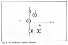
I think the following ones can be considered as predecessors in differential version of your Fet design. They were called enhanced common collectors and the first of them was used in some IC designs.
I tried something similar to your Cadibu design twenty years ago, I never could make it work properly. My fault probably.
I think the following ones can be considered as predecessors in differential version of your Fet design. They were called enhanced common collectors and the first of them was used in some IC designs.
Attachments
Hi Hugh,
---A device operating in constant voltage AND current delivers rock solid Vbe---
A purist might think that this is not enough, the Vbe of the device is still temperature dependant. So, one day I felt as a purist, I thought of a design where the Vbe would have a temperature regulation according to ideas published in Electronics World. It will uses a CA3045, one of the transistors being the thermal sensor, another one the heater, leaving three devices which can have their temperature kepth within 0.1°C. It remains to test if it will have any sonic virtues, I have not built it yet.
Hi Sebastien,
I am confident your circuit would deliver a very cool performance......
[STOP IT!! STOP IT!!!]
Hugh
I am confident your circuit would deliver a very cool performance......
[STOP IT!! STOP IT!!!]
Hugh
MikeB said:Or, may i introduce "Cadibu"?
Similar performance, but less good dc-offset... But, cheaper.
Mike
MikeB, I tried adding the input filter caps but the overshooting with 1KHz Square waves (32ohm load) did not go away at all. Though it was reduced slightly but the problem was still there. Any other ways I can try to stabilize the cascode?
I'm using the slower 2N5088 2N5087 small signal and MJE253 MJE243 for the output transistors. Simulation is done with TINA Spice.
What did you use as inputfilter? I suggest 1k+10pF. The outputtransistors shouldn't be the problem, but slower transistor might cause problems.
Anyway, i don't know how reliable Tina is.
Anyway, i don't know how reliable Tina is.
forr said:Hi MikeB,
I tried something similar to your Cadibu design twenty years ago, I never could make it work properly. My fault probably.
I think the following ones can be considered as predecessors in differential version of your Fet design. They were called enhanced common collectors and the first of them was used in some IC designs.
Hi forr, interesting circuit, but "quite different" as it does not use a floating cascode to keep Vce of active device constant. Intead, the collector voltage is fixed. (If i understood correctly)
But, you're right, it looks like a predecessor!
About device temperature, as voltage and current are practically constant, dissipation is also constant (on active device). the ccs is another story...
Mike
I think that's a pretty cool circuit!😎
change R6, R8 to 2.2k each, and it drives output load of less than 1K with little distortion.
Have you built it, and if so, how does it sound?
change R6, R8 to 2.2k each, and it drives output load of less than 1K with little distortion.
Have you built it, and if so, how does it sound?
Hi gearheadgene,
edit: and the credits go to PMA, who showed such a concept for an power output stage a while ago.
I tried different values for R6/R8, and little changed. I also have a version with beefier output-Q's and lower R13/R16 to drive headphones. It is a bit tricky to achieve a stable running physical layout, but once I found it I have no more problems.
The sound is *very* good, I use it as a buffer in front of my symasym.
Tight bass, relaxed, sweet but not loose overall sound, probably due to the sziklai outputs. I like it a lot more than a two FET curl/borbely buffer I used for a while.
Rüdiger
Attachments

Hi MikeB,
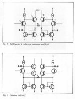
In fig3 I posted, the input transistored has an almost constant current due to the CCS load in the collector and an almost constant voltage across it , thanks to coupled emitters a la Rush.
Note an error in the current mirror connection on the left side.
In fig3 I posted, the input transistored has an almost constant current due to the CCS load in the collector and an almost constant voltage across it , thanks to coupled emitters a la Rush.
Note an error in the current mirror connection on the left side.
I simulated Mike's Q2/Q3 inserted in my circuit and it did wonders. Distortion gets five times lower with a low source impedance (600R) and thrills with high source imp., where it's a hundred times lower.
And all that for additional 10cts. or so!
I have to try it with real parts soon...
Rüdiger
And all that for additional 10cts. or so!
I have to try it with real parts soon...
Rüdiger
I converted MikeB's remarkable JFET follower -
http://www.diyaudio.com/forums/showthread.php?postid=1501336#post1501336
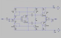
to a BJT version, and removed the current source. Also added 2 simple BJT gain stages in front, wrapped an GNFB loop around it, and Voila! - a simple headphone amp with just 5 BJTs. You can get better results with opamps and integrated diamond buffers, for sure - but this one simulates with superb sonics, probably much better than most CMoys.
With 6v rails, it can deliver about 10 mW into 32 ohms with 0.03% THD20, mostly H2. At lower swings, it can deliver 0.625 mW into 32 ohms with ~0.01% THD20 and H2-H3 ~= 40 dB. It will work with lower rails, but with increased THD - it should be just right for a small discrete CMoy equivalent that runs of 4 AA cells.
http://www.diyaudio.com/forums/showthread.php?postid=1501336#post1501336
to a BJT version, and removed the current source. Also added 2 simple BJT gain stages in front, wrapped an GNFB loop around it, and Voila! - a simple headphone amp with just 5 BJTs. You can get better results with opamps and integrated diamond buffers, for sure - but this one simulates with superb sonics, probably much better than most CMoys.
With 6v rails, it can deliver about 10 mW into 32 ohms with 0.03% THD20, mostly H2. At lower swings, it can deliver 0.625 mW into 32 ohms with ~0.01% THD20 and H2-H3 ~= 40 dB. It will work with lower rails, but with increased THD - it should be just right for a small discrete CMoy equivalent that runs of 4 AA cells.
Attachments
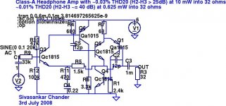

A couple of typos/rendering errors in the schematic, nothing critical. C1 is 1 uF, and feedback DC blocking cap C4 is 0.22 mF, i.e. 220 uF. A wide variety of values will work fine at both locations.
Hi Sivasankar,Original by linuxguru
I converted MikeB's remarkable JFET follower -
http://www.diyaudio.com/forums/showthread.php?postid=1501336#post1501336
to a BJT version ....
now this is telepathy or what? 😀, I didn't sleep well last night, not least because (t)his splendid idea was boggling my mind, too... thinking about realizing it with BJT's and in push-pull... the outcome (from today's simulation, that is) surpasses my expectations by orders of magnitude.
Q1 is running as a follower, with a constant Vce (2 Vbe drops) and a lowish 2mA constant Ic from a simple current source establish the "distortion-free" mode of operation. Same with Q2 etc, opposite polarity. 10R load combining resistors set the ~60mA bias current of the power stages (which dissipate close to 1 Watt each) which are driven by the constant-voltage high local feedback arrangments. The ouput stage is push-pull class-A, the push-pull action tends to cancel even order harmonics which is the dominant type of (the already very low) distortion from the individual sections anyway. Input bias currents also cancel to a big part and output offset is close to zero (a few mV) and stable. Input and output are DC-coupled. Output impedance is 5 Ohms and Zin is 10k Ohms, at audio frequencies.
Operationg from 15V split supplies, it can drive 100R to 20V(p-p) (0.5W) and capacitive loads of 30nF. THD20 for this case (and with a worst-case potentiometer setting of 0.5) is below 0.0002% (2ppm, -113dB)! Under more benign conditions (1k load, 6V(p-p), 2kHz) the values go down to ppb levels. With lower ouput voltages like this 6V(p-p) it can drive 30R, giving 150mW. I'm quite happy with the perfomance for a circuit of this moderate complexity, even when in the real world the specs came out to be 100x worse it still would be quite remarkable, methinks...
- Klaus
Attachments
Klaus,
is this circuit really worth sacrificing your sleep? I do not think it`s especially good sounding but OK, maybe that`s not the main goal.
is this circuit really worth sacrificing your sleep? I do not think it`s especially good sounding but OK, maybe that`s not the main goal.
Lumba Ogir said:is this circuit really worth sacrificing your sleep? I do not think it`s especially good sounding but OK, maybe that`s not the main goal.
You may take note of the fact that there was no mention of sound quality anywhere in the laundry list given in the original post. 😀
se
Lumba Ogir said:is this circuit really worth sacrificing your sleep? I do not think it`s especially good sounding but OK, maybe that`s not the main goal.
... and that was fully intentional, how could I make a guess on that anyway (exept maybe piping some audio through the sim, which is futile for a circuit that doesn't purposely distort 😀)? It is and was intended as a topological study so far, no more and no less, and my only point was to share it since it fits the thread topic.Steve Eddy said:You may take note of the fact that there was no mention of sound quality anywhere in the laundry list given in the original post. 😀
BTW (and Steve might like that 🙂), an intended possible application is high level xformer driving, expecially as the circuit can be modified to give a negative output resistance when a known and stable impedance is at the input (and no pot, then), it's just four resistors more.
- Klaus
- Status
- Not open for further replies.
- Home
- Amplifiers
- Solid State
- best voltage follower, discrete opamp and whatnot