What's the best Vas stage in power amp? Simple one or two transistor? Darlington? Cascode? Complementary sysmetry?...😕
Of course, ''the best'' are: sounding, gain, bandwidth, speed, distortion...
Of course, ''the best'' are: sounding, gain, bandwidth, speed, distortion...
start by looking at Greg's list of potential VAS devices.
You can ruin a VAS simply by picking an unsuitable device.
You can ruin a VAS simply by picking an unsuitable device.
I like a single 2SC3423 in common emitter, carefully compensated either with simple miller or TMC.
Hugh
Hugh
Oh, excuse me! I want to know the topology circuit, not vas devices. Exactly is best Vas topology circuit. Of course, i know vas's transistor must have high Ft, high gain, low Cob, high Vce...
I have been seen GoldMund schema, JFET cascoded input, and simple Vas, but it's have extremely good spec: 250V/uS slew rate, -3dB @ 3MHz bandwidth,...
I have been seen GoldMund schema, JFET cascoded input, and simple Vas, but it's have extremely good spec: 250V/uS slew rate, -3dB @ 3MHz bandwidth,...
Here's a VAS design I came up with a while ago that I like the look of, although I haven't tried it. It's fast and offers clean clipping with rapid recovery.
There's a few key points:
A) None of the VAS transistors ever saturate or switch off.
B) If Vbias is set correctly, it provides symmetrical current limiting.
C) Due to (A) above, voltage at the base of Q2 stays almost constant, even when the output is clipping.
Regards - Godfrey
edit: p.s. Here's a version with a current mirror, hastily cut out from a complete amp schematic before I run out of edit time. It needs clipping diodes too.
Attachments
Last edited:
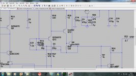
Some ideas there Godfrey. I especially like the collector resistor R1. This doubles up as a current limiter as well.
Does R1 act similarly to Puefue's "magic" resistor? i.e. trying to maintain constant power dissipation.
Does the compound current route R9+R2 as the input collector load, change the way the VAS works?
Would a pair of 25V Zeners from the +-30Vdc supply rails work as the voltage limiting +-25V references?
Or.
Would it be better to run the next stages @+-25V and then the VAS limit would match the next stages capability?
Last edited:
My Ovation 250 uses collector resistors as Godrey shows in a beta enhanced cascade config. However, I did not implement the anti saturation networks as he has done. For my reduced implementation, I can say it sounds pretty good (note: my overall configuration is balanced, but Godfrey's enhancements can be applied just as easily)
In principle its a cascoded darlington. How does it perform linearity wise compaired to beta enhanced. I have found them to be inferior although there aint much in it. Also its not a straight forward comparison.
The cascode reduces miller effect which is true but it doesnt reduce the intrinsic Cob of the vas, the capacitive effect is simply transfered to the cascode device where alas it is smaller but now you have darlington and twice the Cob in the vas. The lower output impedance of darlington will however have lower distortion but this only in the low frequencies, when Cob comes into play at high frequencies it will be inferior. I guess its a poison to pic. If your darlington has perhaps infinite hfe I guess at some point the impedance will be the determining factor. Maybe a darlington where the first transistor is a cfp would swing it in favour at high and low frequencies.
It is important to keep in mind there is no single “optimum VAS” – the rest of the amplifier circuit determines if some “enhancements” have any impact or are swamped by source/load effects
Self (latest edition), Cordell’s Audio Power Amplifier books are great resources
The Groner http://www.sg-acoustics.ch/analogue_audio/power_amplifiers/pdf/audio_power_amp_design_comments.pdf looks at a couple of Self’s book’s suggestions
http://www.essex.ac.uk/csee/research/audio_lab/malcolmspubdocs/J10 Enhanced cascode.pdf is essential to understand “cascode” variations – even if Hawksford didn’t invent or properly cite the origins of the circuits he shows
If you use current mirror on diff pair collectors, triple output stage for low VAS loading then VAS improvements like beta enhancement, cascoding can have visible effects
“beta enhancement” can be done with a follower between mirror and VAS Q, or similar effect can be had with small signal MOSFET VAS – which then needs cascoding
“proper” cascoding requires VAS degeneration R, returning/recycling the common base Q base current – well explained by Hawksford
really high gain, linearity VAS then deserve 2-pole compensation to make use of the gain to linearize more of the amplifier – “TMC” is an option but traditional 2-pole splitting of the Miller C gives largely equivalent results and greater improvement of input diff pair linearity
Cordell's recommended THD @ 20 kHz can be more revealing of AC linearity limitations than traditional 1 kHz test
Last edited:
jcx, yes I recognize quite a few of the valid points you raise.
Homodder, the beta enhancement devices are small signal and should be selected also for low Cob. However, since they are usually run into the cascode, their collector base voltages are held constant. Thus, I do not see the Cob issues you raise: only the cascode Cob remains the issue, for which there are a number of fine candidate devices.
With this construction, the very high local loop gain coupled to the miller (or TMC) comp around the VAS stage means you can get non- linearity down to very low levels in my view.
Last edited:
I agree Jcx, its not such a straightforward comparison but with same outputstage beta enhanced vas offers more simply because it hits harder where its needed, its simple to have low distortion at low frequencies but where it matters most is what happens after 1 khz where in many designs the distortion soars. Some say it doesnt matter at these high frequencies but they dont take into consideration what happens to IM distortion when you mix a 10 Khz and a 300hz signal.
The TPC TMC comparison has been beaten to death, but Edmond is right, TMC has more benefits and it is more effective than TPC although by not much, however it reduces the distortion where its most needed, in the outputstage.
The TPC TMC comparison has been beaten to death, but Edmond is right, TMC has more benefits and it is more effective than TPC although by not much, however it reduces the distortion where its most needed, in the outputstage.
Having the base collector voltage held constant doesnt remove the intrinsic Cob, this can not be removed in any way with circuitry, its device dependent. What cascoding does is remove the miller multiplying effect. With a darlington the two devices s intrinsic cob add up, not so when the beta enhancer is grounded.
You can try this with sim and see the effect.
You can try this with sim and see the effect.
I don’t think the proponents of TMC give the stability issue enough emphasis – in fact I suspect most are ignorant of the potential gotcha in TMC loop stability from the positive feedback around the output stage
TMC is potentially dangerous in inexperienced hands - the "single pole" global outer loop gain gives well damped step response - which is in this case insidious - since it doesn't give the expected stability margins we associate with the damped step response from dominant pole compensated amplifier most are familiar with
also the intercept frequency measured in the global loop is again not as indicative of stability margin as usual for the true single dominant pole case despite appearances - so eyeball or rule of thumb selection of TMC compensation frequency can lead to dangerously low stability margins
http://www.diyaudio.com/forums/soli...lls-power-amplifier-book-134.html#post2420438
Last edited:
I was playing with the spice model of a "mx-50" rip off from China. The e-bay schematic included a darlington VAS, what I got did not. Putting the darlington back in lowered distortion by 30 dB. I modeled a cascode but it was not as effective. This is only by simulation, not by ear. I bought these things so I would have a cheap amp to muck with. Cheap parts, cheap design, cheap price. I got the value I paid for, but I wish it had the darlington so one less hack to the boards.
What I have learned in the simulation, is small details make really big differences. Just topology does not guarantee performance. My Rotels have a simple single transistor VAS and sound just fine.
The gentlemen who have been helping my understand amplifiers would probably say something about a fully complementary cascode darlington with current mirror ccs and boosted supply rails, or that the input tube LTP can drive the KT88's just fine, thank you.
I use a bog standard NPN with a resistor and preset in the base circuit.
However one trick I learned from blown up amps is to put a zener across the VAS to ensure the voltage cant go open circuit. Care needs to be taken tho, too small a zener and you could get crossover distortion and too high a value will blow up the output transistors.
However one trick I learned from blown up amps is to put a zener across the VAS to ensure the voltage cant go open circuit. Care needs to be taken tho, too small a zener and you could get crossover distortion and too high a value will blow up the output transistors.
- Status
- Not open for further replies.
- Home
- Amplifiers
- Solid State
- Best VAS?