Agree this wire-method is most suitable for tubed amps.Oh yes and I use the long ground wire method in guitar amps as mentioned by tubee.
When i place an circuit design on perfboard, i use also a relative thick Gnd wire (1.5 mm) or create a broad Gnd layer on middle line of PCB, it forms a star again.
Here is my first pcb design made on PC: http://www.diyaudio.com/forums/showthread.php?postid=858307#post858307
The Grounding Issue
I've mixed up some of my schematics. . .
My DC power supply for testing has everything tied to earth ground.
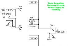
Most of my audio equipment is using a floating ground.
Some of the Rane equipment has a ground lift switch to allow
signal ground to reach earth ground through a passive network
or not connect to the earth ground. But the chassis is always
connected to earth ground in a three prong situation. The
signal ground is it's own star or bus.
I've mixed up some of my schematics. . .
My DC power supply for testing has everything tied to earth ground.
Most of my audio equipment is using a floating ground.
Some of the Rane equipment has a ground lift switch to allow
signal ground to reach earth ground through a passive network
or not connect to the earth ground. But the chassis is always
connected to earth ground in a three prong situation. The
signal ground is it's own star or bus.
Attachments
Grounding Diagram
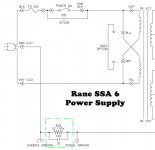
I guess we can talk about the same thing if we look at the same
diagram. . .uploaded is a diagram of a power supply with some
numbered switches. . .
Potential unsafe mains schematic removed.
I guess we can talk about the same thing if we look at the same
diagram. . .uploaded is a diagram of a power supply with some
numbered switches. . .
Potential unsafe mains schematic removed.
Switch Locations 2
Switch four and five closed would have the earth ground equal
to the chassis ground. . .the transformer electrostatic shield/case
would also be tied to earth ground. . .the signal ground would
remain floating.
Switch four and five closed would have the earth ground equal
to the chassis ground. . .the transformer electrostatic shield/case
would also be tied to earth ground. . .the signal ground would
remain floating.
Switch Locations 3
Switch 2, 4, 5, 6 would be a pseudo-floating ground. . .signal ground
would have to go through the passive network. . .
Switch 2, 4, 5, 6 would be a pseudo-floating ground. . .signal ground
would have to go through the passive network. . .
Switch Locations 4
All switches closed would tie earth and signal and chassis and
power supply together. . .this is how my bench top DC power supply
is wired. . . but not intended for audio signal use. . .
All switches closed would tie earth and signal and chassis and
power supply together. . .this is how my bench top DC power supply
is wired. . . but not intended for audio signal use. . .
Hi Gni,
I have asked the Moderators to delete post24 due the potentially fatal consequences if followed by some inexperienced builder.
Find a less dangerous way to explain your reasoning.
I have asked the Moderators to delete post24 due the potentially fatal consequences if followed by some inexperienced builder.
Find a less dangerous way to explain your reasoning.
Switch Locations 5
If all switches are shut. . . nothing bad will happen.
Some equipment does operate in such a fashion. I admit that it
would be a specially designed circuit. . . the engineer would
have to know what they are doing. . .but this diagram is to be
used to discuss the some likely grounding schemes.
If all switches are shut. . . nothing bad will happen.
Some equipment does operate in such a fashion. I admit that it
would be a specially designed circuit. . . the engineer would
have to know what they are doing. . .but this diagram is to be
used to discuss the some likely grounding schemes.
I trust Andrew in this and removed the picture in post #24.
Don't let this withhold you guys to find a better solution for the PSU wiring.
/Hugo
Don't let this withhold you guys to find a better solution for the PSU wiring.
/Hugo
Re: Re: Earth Ground to Signal Ground Connections
So, is this correct grounding scheme easily described and has it been depicted in a past post?
Regards, Mike.
AndrewT said:Yes, I did it wrongly until recently, because I didn't know any better.
Allow yourself to open the door to the possibility that there is a better way.
So, is this correct grounding scheme easily described and has it been depicted in a past post?
Regards, Mike.
Working on new universal Schem atic
Will post new schematic for education purposes only. . .so we can
talk apples to apples.
Will post new schematic for education purposes only. . .so we can
talk apples to apples.
Hi Gni,
try using letters (or some other short code) to describe different locations on the diagram.
DO NOT show switches in the safety earth wiring.
try using letters (or some other short code) to describe different locations on the diagram.
DO NOT show switches in the safety earth wiring.
Working
Working on it. . . .give me anther day. . . had recording project
that got in the way. . .but paid some bills. ; - )
Working on it. . . .give me anther day. . . had recording project
that got in the way. . .but paid some bills. ; - )
Supporting Evidence
http://www.equitech.com/support/wiring.html
"When chassis and audio grounds are connected to the center tap of a balanced AC isolation transformer, they are referenced to the mean AC voltage differential which is equivalent to the zero crossing point of the AC sine wave. There is no current or voltage on the center tap -- here is a clean single-point ground reference for audio. Virtually all chassis, audio grounds and shields can be referenced back to this single point. The center tap of the transformer is then grounded to earth for safety and to shunt any electromagnetic and radio frequency interference away from shields and chassis."
Hi,
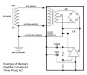
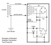
the diagrams in post 36 and post 37 are absolute balderdash.
Any manufacturer offering that solution should be strung up.
And you suggesting they are "standard" compounds the error.
the diagrams in post 36 and post 37 are absolute balderdash.
Any manufacturer offering that solution should be strung up.
And you suggesting they are "standard" compounds the error.
AndrewT said:Hi,
the diagrams in post 36 and post 37 are absolute balderdash.
I agree that as drawn there are issues with the schemes presented. The picture translates to using the chassis as a plane type ground for all supply-input-output-safety grounds. the results of this would be a problem to stabilize and the resultant sound would be two-D and congested. There is no way to eliminate interference between the various functional blocks.
I wonder, having attempted to present such diagrams in the past, what the true intent was. I am also curious to examine the correct approach to component grounding.
Andrew, can you post a link to the descriptions you mentioned as being a guide for your efforts? I've been to the Self site but other than references to grounding and cabling diagrams I do not find the overall approach that you mention. I've built a couple of chip amps to experiment with and this input would broaden my experiments.
Regards, Mike.
- Status
- Not open for further replies.
- Home
- Amplifiers
- Solid State
- best Place for Star Ground?