I’m just a fly on the digital wall here, thankful that this topic is being discussed. I am hoping that these two links could be reviewed as examples of circuit grounding.
Both illustrate star grounds The ‘groundtutor’ illustration is badly drawn but once beyond getting around that it is well written.
http://www.geofex.com/Article_Folders/stargnd/stargnd.htm
http://www.sonic.net/~ktstrain/Groundtutor.htm
Both illustrate star grounds The ‘groundtutor’ illustration is badly drawn but once beyond getting around that it is well written.
http://www.geofex.com/Article_Folders/stargnd/stargnd.htm
http://www.sonic.net/~ktstrain/Groundtutor.htm
More Examples
Those were the right kind of links.
I am attempting to draw several circuits that people can refer
to so they can correctly ground their system.
Each of the following grounds is important. . . some should be connected
and some should not. . . there is an order that they should be connected.
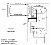
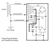
Some electronics have only two prongs; some contain three.
Earth Ground
Chassis Ground
Power Supply Ground
Signal Ground
Those were the right kind of links.
I am attempting to draw several circuits that people can refer
to so they can correctly ground their system.
Each of the following grounds is important. . . some should be connected
and some should not. . . there is an order that they should be connected.
Some electronics have only two prongs; some contain three.
Earth Ground
Chassis Ground
Power Supply Ground
Signal Ground

The difficulty with the image in post #37 as well as the derivatives is that I mentioned earlier -- the combine elements that are purely a circuitry schematic with the mechanical layout of the wiring. If you were to enter these as drawn in to a spice program (such as LTspice) think about what would be defined as a node. The enclosure and everything wire connected to it would be treated as a single node point. The other drawings are to some degree or another in the same boat.
This is not a criticism of the approaches but rather to point out that even a perfectly sound ground scheme is a b**ch to describe diagramaticly. It seems like it ought to be simple, but . . .
This is not a criticism of the approaches but rather to point out that even a perfectly sound ground scheme is a b**ch to describe diagramaticly. It seems like it ought to be simple, but . . .
Thank You
That is a good point. . . I guess I need to draw in such a way as
to absolutely define each point. Example: point A is a connection
to the chassis, circuit path DE is a bus bar. Something like that might
help all.
I work on it.
That is a good point. . . I guess I need to draw in such a way as
to absolutely define each point. Example: point A is a connection
to the chassis, circuit path DE is a bus bar. Something like that might
help all.
I work on it.
Hi,
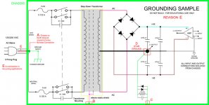
this latest version of your grounding has the amp signal return, power return, decoupling return, Zobel/Thiel return, and the speaker return omitted.
I return to my previous advice.
The audio ground should not be located on the junction between the smoothing caps.
A new question:
Where is the best place to take the electrostatic screen.
to safety earth,
to chassis but separate from the safety earth,
to audio ground or
to some other?
Comment:
1.
I think I can see a little green plimp connecting chassis to safety earth.
Can you make this much more clear? Maybe best by showing a separate connection from chassis to GROUND (green).
2.
the single pole mains switch is not permitted in the UK on 240Vac. It may not be allowed anywhere that exceeds 120Vac.
We must use a two pole switch with both the live AND the neutral switched.
Good gni...you really know what you are telling us
thank you by the effort to show us how the things works....different than show yourself, you are contributing.
Despite my 46 years of electronics and some Television Stations designed....i had pleasure listening you....i have learned some.
regards,
Carlos
thank you by the effort to show us how the things works....different than show yourself, you are contributing.
Despite my 46 years of electronics and some Television Stations designed....i had pleasure listening you....i have learned some.
regards,
Carlos
Hi Gni,
It is good to see all theory together in one drawing.
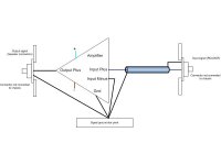
For myself, I am always trying to decide what to do with the incoming signal to the amplifier. (mono-amp)
Just to add my two cents, this is how I do it now.
(In Pass mono-amps. Doing the same in my pre-amp was a lot, lot more difficult)
Greetings, Harry
It is good to see all theory together in one drawing.
For myself, I am always trying to decide what to do with the incoming signal to the amplifier. (mono-amp)
Just to add my two cents, this is how I do it now.
(In Pass mono-amps. Doing the same in my pre-amp was a lot, lot more difficult)
Greetings, Harry
Attachments
Hi GNI,
Regarding revision E;
You connect a number of wires to the chassis (on points B and C). Are these wires in your opinion as short as possible, or are these wires better connected to point A (where the chassis is earthed on the entry-point)
Greetings, Harry
Regarding revision E;
You connect a number of wires to the chassis (on points B and C). Are these wires in your opinion as short as possible, or are these wires better connected to point A (where the chassis is earthed on the entry-point)
Greetings, Harry
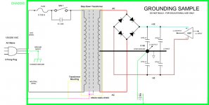
Chassis Connections
It seems to be the opinion of electrical engineers and others that
the earth ground connection be at the point of entry of the chassis.
The transformer mounts are bolted to the chassis (but not at the
point of entry). I could see a point of bringing the AC mains into
the chassis very near the mounting bolts of the transformer so as
to create the earth ground at the same physical point on the chassis
as the transformer bolt.
As for the connection of the star ground through the passive network
to ground. . .yes as short a humanly possible. I would want to connect
it at the same point as the transformer mount. . .I think others
disagree.
I'm trying to make a diagram that will meet the 'standards' of most
countries.
I liked your simple diagram of connections for amplifiers.
Hi,
two question for the Forum:
1. where is the best place to connect the electrostatic screen? or does it depend on what follows.
2. Is it safe for any amateur to build a double insulated amplifier and to use a two pole plug and socket to connect to the mains?
or is this an accident waiting to happen?
Gni,
things have moved on. We are almost in agreement!
Can you move the audio ground away from the common lead linking the smoothing caps. This is one of the worst places for it.
Go and read
http://www.diyaudio.com/forums/showthread.php?s=&threadid=90728 post 57 & 59 and some others of general interest.
I realise that two pole mains switching must be foreign to you, but I meant a single two pole switch not a pair of two pole switches. One pole on each of the live and neutral is sufficient.
Couple of my opinions...
1) Regarding safety wire connection:
"It seems to be the opinion of electrical engineers and others that the earth ground connection be at the point of entry of the chassis." I Agree in most cases, however an overlooked fact is that if the mains is brought into the chassis with a solid wire then the safety wire should be left longer than L and N wires. It should be the last connection that breaks under tension directed to mains cord.
2) Star ground point at main filter capacitors:
I would not recommend this. This place is infested by high charging currents.
3) Ideally, signal and supply ground returns should have separate buses to star ground point. In the ground bus, higher current returns should be located physically closer to the star ground point than lower current returns.
4) About "Loop breakers"
While there are many opinions about these I have always found more effective to connect the star ground point to the chassis. Since I fail to see that the basic loop breaker circuit would contribute anything at the field of safety I'd suggest anyone to try both setups - with and without.
Hi,
I completely agree your points 1 thro' 3. Well put.
I completely disagree on connecting the safety earth to the audio ground.
ALWAYS use a disconnecting network.
I completely agree your points 1 thro' 3. Well put.
I completely disagree on connecting the safety earth to the audio ground.
ALWAYS use a disconnecting network.
teemuk said:
4) About "Loop breakers"
While there are many opinions about these I have always found more effective to connect the star ground point to the chassis. Since I fail to see that the basic loop breaker circuit would contribute anything at the field of safety I'd suggest anyone to try both setups - with and without.
Maybe I have misunderstood, but I think the point of those circuits are to break the loop for hum, not to serve any safety purpose (which they obviously don't).
Hi Christer,
there is a BIG safety issue with the loop breaker.
The Safety Earth is ONLY there to protect the user if there is a mains fault.
The audio ground is ONLY there to keep the audio part of the amp working properly.
The Safety Earth and the audio ground do not need to be connected for ANY audio reason.
Unfortunately, the senario of a mains fault making part of the audio circuit LIVE (a broken live wire touching an uninsulated part of the PCB or rear of an RCA etc) is very possible.
When this happens the risk if electrocution is high unless the unit can be forced to break the mains supply. The mains fuse is there to do this. But the escape route from the faulty live wire into the audio circuit to ground can only be via the disconnecting network to the Safety Earth.
The fault current to ground can approach kA for a very few mS. the disconnecting network MUST survive long enough for this fault current to break the fuse.
If the disconnecting network failed before the fuse melted then the faulty unit stays live and if someone were to touch an exposed conductive part then the consequences could be fatal.
What happens when the stereo mysteriously goes silent? Would you get up and twiddle with it? Would you pull out an RCA or two?
Or would you go straight to the wall socket and pull the plug? I'll leave you to work out which is less safe and which is more likely.
On closing, I can understand the thought that a direct connection between safety earth and audio ground is the safe way to do it, but I cannot agree it's efficacy when a better alternative is available.
Christer said:
Maybe I have misunderstood, but I think the point of those circuits are to break the loop for hum, not to serve any safety purpose (which they obviously don't).
You are absolutely right. The circuit will "break" ground loops by reducing loop currents to small value. The basic circuit (just cap and resistor in parallel) is quite unsafe and requires a high power diode bridge which acts as a path for currents in fault condition.
What I find appalling in loop breakers is that they also break the solid connection between chassis earth and ground point. This can result into increase of EMI interference or increase the effects of ground loops that may exist within the amplifier circuit itself. Later are, naturally, due to bad design in the first place but I've seen more than couple of amps that required a solid connection between ground and chassis (earth) in order to stop annoying hum present even without external signal sources.
As I said, choice is yours since it's not related to safety issues: You can try both setups.
- Status
- Not open for further replies.
- Home
- Amplifiers
- Solid State
- best Place for Star Ground?