No pun intended Rick, I was only trying to provide a suggestion based on "magnetic wire" you referred to in one of your previous posts, that's all. I assumed you used a steel wire...
Nick
Nick
Thanks Nick, I was just referring to magnet wire, the thinly coated wire used in winding coils for transformers and inductors. I have found that steel wire sounds bad, bright and harsh. I wish it did not, as I have a lot of silver platted steel wire that I cannot use for audio.
Rick
Rick
answers to Nick and abrayalito
Nick,
There is not any fluid of any kind inside the LME metal can HA devices. In fact I have never seen that in a metal can device before. The Bob Pease comments, that I listed in my last posting, are the most likely reason for the improved / perceived audio improvement of the cans over the dip/SO packages.
abrayalito,
Here is the excerpt from my last posting describing what an actual Faraday shield is...
Faraday shields include both electro-static and electro-magnetic shielding techniques.
Best Audio Regards Everyone,
audioman54 / Mark
Here is the excerpt from my last posting describing what an actual Faraday shield is...
Faraday shields include both electro-static and electro-magnetic shielding techniques.
Thanks for responding but that does not answer the question I put which asked how the metal can differed from a Faraday shield.
Nick,
There is not any fluid of any kind inside the LME metal can HA devices. In fact I have never seen that in a metal can device before. The Bob Pease comments, that I listed in my last posting, are the most likely reason for the improved / perceived audio improvement of the cans over the dip/SO packages.
abrayalito,
Here is the excerpt from my last posting describing what an actual Faraday shield is...
Faraday shields include both electro-static and electro-magnetic shielding techniques.
Best Audio Regards Everyone,
audioman54 / Mark
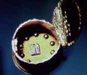
The jpg of a metal can with its top cut-off attached... the small, thick metal cylinder, with the rigid, extruded top & the thick bottom metal plate, PLUS the way the IC die is connected to the pins should definitely make that die less prone to mechanical oscillations, compared to plastic and even ceramic encapsulation, so I tend to disagree with you when you say that immunity to mechanical oscillations has nothing to do with superior sound of metal can IC’s, compared to their plastic / ceramic siblings.
Nick
Attachments
Why in Primare Spa21 iv after pcm1738 is made with ne5532 and lpf is opa2132 ? Now i want use muses and really dont know if i should use 8920 instead ne and 8820 / opa ??? or in primare way - slow bipolar for iv and ,,quick,, jfet for lpf....
How about LME49721
Hi, I discovered this chip not so long ago, did anyone used it? It seems to be perfect for I/U conversion. Also, I'm ordering two of them, so i might give you some impressions about them.
Hi, I discovered this chip not so long ago, did anyone used it? It seems to be perfect for I/U conversion. Also, I'm ordering two of them, so i might give you some impressions about them.
Why in Primare Spa21 iv after pcm1738 is made with ne5532 and lpf is opa2132 ?
Because that DAC is integrated inside the amplifier and they don't care much about providing an excellent DAC section inside their integrated amplifier. I bet they still want to keep selling the stand-alone DAC's... also, the mellow sounding 2132 is hard not to like.
If you want to save the time and money, go straight to the best the OP's can provide: AD811 as I/V and LM6172 as lpf/buffer. Just be carefully when implementing AD811. Also, the noise around that DAC PCB will have to be well controlled. The noise around that DAC will have to be exceptionally low.
Nick
Muses sounds fantastic, I used mmuses02 in my accuphase p7100 clone and it makes very big upgrade to oryginal njm. But I,m not sure where use jfet and where bipolar...in primare spa21
you forget to mention the noise of AD811 - is simply has high current noise, even more at the -input
CFA do have an advantage in low input Z when used in DAC I/V, and they all have the high current noise cost at the -input
CFA are not good candidates for rolling into an existing circuit not designed for them - they have different stability relations than the VFA the circuit was designed for
CFA do have an advantage in low input Z when used in DAC I/V, and they all have the high current noise cost at the -input
CFA are not good candidates for rolling into an existing circuit not designed for them - they have different stability relations than the VFA the circuit was designed for
the circuit can be changed
dynamic impedance seen by DAC output can be very low
I didn't say it was easy...
dynamic impedance seen by DAC output can be very low
I didn't say it was easy...
Why I/V stage in audio DAC require fast settling opamp (circuit, compensation)?
It is not SHA, so it do not need to reach input level precisely, right?
Is it because IPS=LTP resides higher distortion during/before settle to adequate differential input level?
It is not SHA, so it do not need to reach input level precisely, right?
Is it because IPS=LTP resides higher distortion during/before settle to adequate differential input level?
Fast settling time seems to be one aspect but the nature of the settling transient is very important too. In theory only a perfectly exponential settling response introduces no non-linearities.
I think the bypass capacitors for the sound I/V stage is very important and can completely
change the character ...
my Favorite is MUSES8920 (jfet) and OPA2604(fet) for the area, with the coefficients Amps
Various materials capacitance can change the character of the opamp .
I think Not good the Opa627 at this point because they did not have any color . It's like water color.
It must be in the original color made of the sound I/v stage created and chips with good natural color need hear this point .
627 for the transmission and amplification discoloration due to higher stage after I/V stage (dac) is perfect .
So I think fast setlling time to color the sound is not very important for I/v stage after DAC.
Thank you. Afshin
Last edited:
Gentlemen,
I am still quite happy with my rather simple and straightforward I/V converter solution, based on a LME49713 current feedback OpAmp and a cheap 10:1 audio transformer. It employs a simple offset compensation servo loop making capacitors in the audio signal path unnecessary.
The I/V converter works within a NOS DAC-AH, but should do as well with other current output DACs.
Design goals were straightforward:
The decision for the small budget audio transformer was, give it a try before buying one of these really expensive pieces. I was positively surprised and so I stuck to it. If you don't like transformers, you may want to use a simple passive 10:1 voltage divider (something like 10K+1.2K) instead, but I haven't tried that. However, a divider network instead of the transformer might setup the carefully tweaked OpAmp overshoot compensation in some unpredictable way, so just be aware of that.
I am still quite happy with my rather simple and straightforward I/V converter solution, based on a LME49713 current feedback OpAmp and a cheap 10:1 audio transformer. It employs a simple offset compensation servo loop making capacitors in the audio signal path unnecessary.
The I/V converter works within a NOS DAC-AH, but should do as well with other current output DACs.
Design goals were straightforward:
- DAC output should see rock steady zero impedance current source point.
- OpAmp should have fastest rise times available
- No fancy filter circuitry
The decision for the small budget audio transformer was, give it a try before buying one of these really expensive pieces. I was positively surprised and so I stuck to it. If you don't like transformers, you may want to use a simple passive 10:1 voltage divider (something like 10K+1.2K) instead, but I haven't tried that. However, a divider network instead of the transformer might setup the carefully tweaked OpAmp overshoot compensation in some unpredictable way, so just be aware of that.
maybe some serious theory please?
Could someone explain why? I think the low input impendence will be good for virtual ground as it is an output of an inner amplifier with a resistor.
Many thanks. I just want to do some mod as I consider a CFB OP would be the best I/V stage choice?
1. inverting input of the current feedback OP is a poor choice for virtual ground summing
Could someone explain why? I think the low input impendence will be good for virtual ground as it is an output of an inner amplifier with a resistor.
Many thanks. I just want to do some mod as I consider a CFB OP would be the best I/V stage choice?
CFA do have an advantage in low input Z when used in DAC I/V
I agree with this,but is there someone can do some serious analysis on this?
Will low-z inverting input CFA benefit from it when used in I/V convention?
Could someone explain why? I think the low input impendence will be good for virtual ground as it is an output of an inner amplifier with a resistor.
Many thanks. I just want to do some mod as I consider a CFB OP would be the best I/V stage choice?
Ithink this has been discussed before in this forum. It's not a very good low impedance path. The impedance varies with frequency (a lot!).
Could someone explain why?
I have no idea why. Perhaps Nick will explain his statement, it looks to be counter to established theory as I understand it.
I think the low input impendence will be good for virtual ground as it is an output of an inner amplifier with a resistor.
Quite so, therefore its likely to be stable and relatively low impedance up to higher frequencies than for a VFB amp which is relying on global NFB for its low impedance.
Many thanks. I just want to do some mod as I consider a CFB OP would be the best I/V stage choice?
Myself I prefer a step-up transformer over any CFB or VFB amp I've tried. Not by a small margin either.
- Home
- Source & Line
- Digital Line Level
- Best opamp for I/V conversion? (DAC)