.I thought he just wanted to unsolder the existing 3 reg and replace it another, but better 3 pin reg.
LT3042 for positive voltage.
And what is LDO PSU for negative voltage ? Pair for LT3042 ?
.
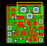
I have made a tiny layout for the npn circuit in the data sheet.
I have no idea of a negative version that does not have at least
2 op amps.
It will take some time until I can test that. A lot of stuff in the pipeline
in front of it.
regards, Gerhard
OK, I gave it a bypass. I might need it for a 3 GSPS ADC.
< https://www.flickr.com/photos/137684711@N07/29197476530/in/dateposted-public/ >
and a preliminary check of noise voltage density without a layer of shielding
and low frequency noise that may stem from the pre-amp:
< https://www.flickr.com/photos/137684711@N07/29452163806/in/album-72157662535945536/ >
For the +/- version, I have an idea wit 1 op amp in the meantime.
regards, Gerhard
My technical knowledge is pretty low level so I'd be interested in what you guys think of this:
0.8uV Ultralow noise DAC power supply regulator +-9/12/15V 1.5A*x2 - DIYINHK
0.8uV Ultralow noise DAC power supply regulator +-9/12/15V 1.5A*x2 - DIYINHK
.My technical knowledge is pretty low level so I'd be interested in what you guys think of this:
0.8uV Ultralow noise DAC power supply regulator +-9/12/15V 1.5A*x2 - DIYINHK
LT3042 for positive voltage.
And what is LDO PSU for negative voltage ? Pair for LT3042 ?
.
I think, that there is no negative pair for LT3042 ?!
.
If your negative supply comes from a separate isolated secondary and rectifier, you can use the LT3042 as a negative regulator.
If your negative supply comes from a separate isolated secondary and rectifier, you can use the LT3042 as a negative regulator.
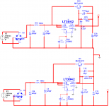
Hi, Can this work?
Dual 3042 with external NPN for higher current demand.
Attachments
That is the general idea, but the way the transistor is added looks a bit goofy to me. Do you have a source for this schematic?
That is the general idea, but the way the transistor is added looks a bit goofy to me. Do you have a source for this schematic?
Hi,
It's from LT3042 Datasheet.
BR,
Eric
Attachments

It's from LT3042 Datasheet.
same circuit as mine in post #542.
regards, Gerhard.
If you want the layout as .pdf or Gerber, just say so.
It is not a beginner's project wrt etching / soldering.
Attachments
Last edited:
same circuit as mine in post #542.
regards, Gerhard.
If you want the layout as .pdf or Gerber, just say so.
It is not a beginner's project wrt etching / soldering.
No, I don't. You're humiliating. I can make layout by myself. I post the schematic to discuss the dual 3042 for pos/neg rails.
Gerhard is just offering help. Engineers and DIYers are all lumped together on this site.
Since the schematic comes from the datasheet I see no problem with your schematic.
Since the schematic comes from the datasheet I see no problem with your schematic.
Hi, Can this work?
Dual 3042 with external NPN for higher current demand.
Pretty sure the negative regulator will blow up. The positive-side regulator is fine, of course. But you have not properly translated the positive circuit to a negative one. On the negative regulator the ground is now positive--which is wrong. The most negative point is the -15v rail so that would need to serve as ground for negative regulator. That is my understanding. In particular, Gnd, ILM probably need to be tied to -15v. Googling "positive regulator for negative supply" or similar reveals this to be a bad idea.
Last edited:
Not really, the + and - of the negative reg are decoupled so a few hundred pF of trafo winding capacitance will not have any effect. Since the trafo winding is floating, ground can be either output point.
Gerhard is just offering help. Engineers and DIYers are all lumped together on this site.
Since the schematic comes from the datasheet I see no problem with your schematic.
The negative side is NOT from the datasheet. Please look again at what was posted.
Hi,
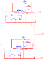
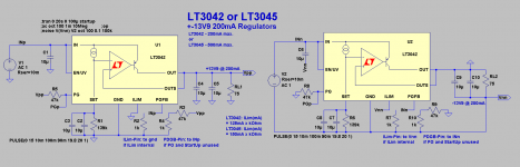
I agree with fortitudine that the Ilim and G Pins of the negstive side should be connected to the -15V line and not to gnd.
Other than that the crcuit should work.
For Your notice .. there's a stronger brother of the LT3042 (200mA) the LT3045, specced with 500mA.
jauu
Calvin
I agree with fortitudine that the Ilim and G Pins of the negstive side should be connected to the -15V line and not to gnd.
Other than that the crcuit should work.
For Your notice .. there's a stronger brother of the LT3042 (200mA) the LT3045, specced with 500mA.
jauu
Calvin
Now I see it, the Ilim and G pins on the negative side should go to the negative rail.
Hi,
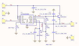
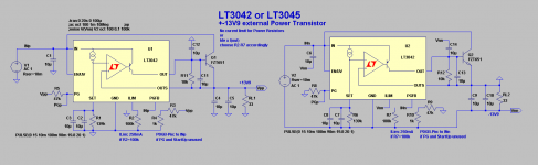
according to the above, here's the schematic. Can somebody kindly perform a LTSPICE for this? as Multisim is not supporting LT3042.
Eric
Attachments
Not me, my computer is dead. Although the LT3042 model wasn't working for me even when it was alive.
Hi,
zip-file attached 😉
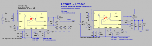
Using a external transistor one needs to either omit with the current limit feature and risk a possible damage of the power transistors in case of a failure situation, or one needs to reavaluate the ILim-Resistor values.
The sim results in +-13V9 output voltages as the setting resistors are chosen to be 139k (100+39k).
This is done as the input voltages are assumed to be 2x 15V.
A Input-Output differential of 1.1V is sufficient for the non-boosted circuit but on the edge for the boosted ... a bit more voltage differential should be beneficial.
jauu
Calvin
zip-file attached 😉
Using a external transistor one needs to either omit with the current limit feature and risk a possible damage of the power transistors in case of a failure situation, or one needs to reavaluate the ILim-Resistor values.
The sim results in +-13V9 output voltages as the setting resistors are chosen to be 139k (100+39k).
This is done as the input voltages are assumed to be 2x 15V.
A Input-Output differential of 1.1V is sufficient for the non-boosted circuit but on the edge for the boosted ... a bit more voltage differential should be beneficial.
jauu
Calvin
Attachments
Last edited:
- Home
- Amplifiers
- Power Supplies
- Best low noise regulator?