One other thing that may cloud the issue a bit - SOA curves are usually based on destructive testing but transient thermal impedances are usually calculated from MODELS. Models can be wrong, but measurements don't usually lie. And the reported value forTjmax is usually the hottest spot, which can be 100 degrees hotter than the average on the rest of the die. You could take the same die and run two different thermal simulations and get two different answers.
To get a real answer on the die size, I guess somebody's got to go breaking a few open. The only ones I have are samples from Fairchild, so I've got no reason to suspect fakes. That's usually the only reason I waste a few....
To get a real answer on the die size, I guess somebody's got to go breaking a few open. The only ones I have are samples from Fairchild, so I've got no reason to suspect fakes. That's usually the only reason I waste a few....
Don't mean to dilute the thread, but I have broken open a lot
of trannies.(service related). (mostly MJE/MJ - ON /Toshiba and
NTE direct substitutes.)
I used NTE for awhile,
but had to many re-do's.. Found out after breaking open the NTE
subs ,the die was smaller than the real thing
(fairchild's/ON's/or toshiba's)
I no longer use NTE ,maybe not fakes but definitely inferior to
the more expensive originals.
I,ve had some repairs survive the "NTE world" but drivers
and outputs come back too often.
I wonder if 'multicomp' ,which makes subs for all the MJE/MJ
line at half price, is who really makes NTE ?
🙁 🙁
OS.
Hi ostripper,
Do you know the dimensions of the die in these transistors? I'm especially interested in if there is a size difference between the Toshibas and Fairchilds. What about the MJL3281?
wg_ski:
If you look at swithing MOSFET datasheets though you will see that the transient thermal impedance and pulse SOA curves add up perfectly giving Tjmax when you combine them. The reason? The SOA curve is often based on the modeled transient thermal impedance. One has to be careful with linear operation as these curves do not take into account current crowding that can occur at higher voltages...
Did I understand correctly that you mean the transient thermal impedance curves calculate the temperature of the hottest spot, where the heat is produced, and the non-ideal heat conduction of the die makes most parts of it colder? Or did you mean something else?
OT: What do you like to use for rail switches in high power amps? I found these 300V IGBTs designed for PDP:s and they look pretty useful if you need a bit higher voltage rating (for example if you want to drop rails to 0V and not put the rail switches in series). Saturation voltage at 50A is about 1.5V:
http://search.digikey.com/scripts/DkSearch/dksus.dll?Cat=1376382;keywords=90n30
Datasheet:
http://www.fairchildsemi.com/ds/FG/FGA90N30.pdf
The switching losses are specified like this (at 25 and 125 degrees):
One qeustion.
I understand this is some switching application, like digital transfer.
But what does PDP actually stand for?
Pulse .... D .... Power 😕
http://www.fairchildsemi.com/ds/FG/FGA90N30.pdf
Employing Unified IGBT Technology,
FGA90N30 provides low conduction and switching loss.
FGA90N30 offers the optimum solution for PDP applications
where low condution loss is essential.
The switching losses are specified like this (at 25 and 125 degrees):
Eon Turn-On Switching Loss -- 0.16 -- mJ
Eoff Turn-Off Switching Loss -- 0.72 -- mJ
Ets Total Switching Loss -- 0.88 -- mJ
Conditions:
VCC =200V, IC = 20A,
RG = 10Ω, VGE = 15V,
Resistive Load, TC = 125°C
One qeustion.
I understand this is some switching application, like digital transfer.
But what does PDP actually stand for?
Pulse .... D .... Power 😕
PDP = Plasma Display Panel 🙂
I found this MOSFET too:
http://search.digikey.com/scripts/dksearch/dksus.dll?Detail?name=FDP75N08A-ND
I'm probably going to use those instead, but in series. ~2V of drop (2 in series, rdson recalculated for hot transistor) instead of 1.5V at 50A. Not a big difference and if I decide I'm not going to build this amp I will have a couple of mosfets useful for a lot of stuff instead of IGBTs that are only usable for PDPs or rail switches in high powered class-H amps...
The big transformer in this picture is on it's way:
http://static.pici.se/pictures/rpuxPQUdx.jpg
I'm thinking of rewinding it to give 4 windings of 45V unloaded at absolute maximum line voltage tolerance so I can use my stash of 63V caps.
The trannies I broke open 2SA1943 (fairchild)-2SC5358(toshiba)
were pretty burnt but they had a similar sized die.
were pretty burnt but they had a similar sized die.
Another vote here for the MJL4281/4302 transistors!
Mono Amp built with 5 pairs of them and +/-75V rails for 4 ohms, NO output protection, and didn't blow the output stage when a voice coil blew shorted to nearly 0 ohms at FULL volume. Killed two subwoofers so far with these outputs, and the amp is going strong!
I've also built battery chargers and voltage regulators with the 4281/4302 transistors, with ZERO failures.
However, for somewhat smaller devices, I do have a great interest in the fjp1943/5200 15A TO-220 devices. They would allow an amp with more space left on the heatsink for more devices. Also would be great for smaller projects when you want a super-rugged TO-220 device.
megajocke said:wg_ski:
If you look at swithing MOSFET datasheets though you will see that the transient thermal impedance and pulse SOA curves add up perfectly giving Tjmax when you combine them. The reason? The SOA curve is often based on the modeled transient thermal impedance. One has to be careful with linear operation as these curves do not take into account current crowding that can occur at higher voltages...
IOW, it doesn't model second breakdown. Only temperature rise.
Did I understand correctly that you mean the transient thermal impedance curves calculate the temperature of the hottest spot, where the heat is produced, and the non-ideal heat conduction of the die makes most parts of it colder? Or did you mean something else?
That's exactly what I mean. The die temperature is nowhere near uniform. The parts that get hot are very small and silicon isn't a perfect heat conductor. Combine that with the negative tempco in Vbe and and that's why you get S/B in the first place. More uniform construction, better heat spreaders, and internal ballasting all help. Modern trannies were devloped using those thermal models - you can see what and what not to do in the layouts. Even if your model is off by 15 degrees, you can still spot potential improvements.
OT: What do you like to use for rail switches in high power amps? I found these 300V IGBTs designed for PDP:s and they look pretty useful if you need a bit higher voltage rating (for example if you want to drop rails to 0V and not put the rail switches in series). Saturation voltage at 50A is about 1.5V:
http://search.digikey.com/scripts/DkSearch/dksus.dll?Cat=1376382;keywords=90n30
I just use hexfets for class H. IRF1407, 2907, and more recently the Fairchild 75344. They switch plenty fast enough for any woofer amplifier, and I've never tried to hard switch more than 50V at a time. With quad 63V rails, It was a class-G retrofitted S-Leach type amp so I alreday had upper transistor banks in place.
Now with anything that big it's 3-tier. I've got some of the Fairchild 20N60's around, but I was saving those for experimenting with some bigger SMPS (assuming I can get some decent size cores).
I remember reading an interesting paper about MOSFETs having lower DC soa than their datasheets suggest. Especially the trench types. They did tests with both trench types and standard type mosfets and I remember there were pictures taken with a thermal camera showing non-uniform heating of the die clearly. It was on the net but I can't find it now.
It is very impressive how much bipolar transistor SOA has improved since the early transistors. The second breakdown specs of transistors like MJ(L)2119x come to mind. Sanken 2SC3264 and similar aren't bad either.
It is not surprising the Hitachi lateral FETs were so popular when they came out when you look at the SOA of bipolars of the same vintage. Also the very strong negative temperature coefficient of current and some kind of gate-source latchup at high temperature make them extremely hard to destroy. Little experiment I did last year: http://www.diyaudio.com/forums/showthread.php?threadid=111116
About the rail switches, look here, made a new thread to try to keep stuff related to this collected in one place:
http://www.diyaudio.com/forums/showthread.php?s=&threadid=129162
I guess the task of the transistor determines which is the best to
use.
For sub I use MJE15003/4 or MJE15023/4.. they like to be abused.
but for fullrange,
Toshiba rules .
With the 2SC5358/2SA1986 pair I actually
heard a difference in the sound stage at high volumes.🙂
use.
For sub I use MJE15003/4 or MJE15023/4.. they like to be abused.
but for fullrange,
Toshiba rules .
With the 2SC5358/2SA1986 pair I actually
heard a difference in the sound stage at high volumes.🙂
If the picture you linked to is an example of their product, then they are selling fakes.
I really wouldn't risk eBay for this sort of thing, especially not sellers from China which is where the majority of fakes come from.
I really wouldn't risk eBay for this sort of thing, especially not sellers from China which is where the majority of fakes come from.
And eBay is where you would go
in case if you have bought 100 faked somewhere.
To make somebody else take 'your loss'.
I have said it before.
In the long run, it is the cheapest to buy where you know you get real stuff.
Some company that has served for a bunch of years, without getting a bad name.
With a real address and telephone number 😉
EWorkshop1708 said:Another vote here for the MJL4281/4302 transistors!
Mono Amp built with 5 pairs of them and +/-75V rails for 4 ohms, NO output protection, and didn't blow the output stage when a voice coil blew shorted to nearly 0 ohms at FULL volume. Killed two subwoofers so far with these outputs, and the amp is going strong!
I've also built battery chargers and voltage regulators with the 4281/4302 transistors, with ZERO failures.
However, for somewhat smaller devices, I do have a great interest in the FJP1943/5200 15A TO-220 devices. They would allow an amp with more space left on the heatsink for more devices. Also would be great for smaller projects when you want a super-rugged TO-220 device.
They are good transistors:
MJL4281A MJL4302A from OnSemi. They have better data than 3281/1302:
- a bit faster, 35 vs. 30 MHz fT
- a bit higher gain, 80-250 vs. 75-150 hFE
- a bit better heatsinking, 0.54 vs. 0.625 C/W
- gives 230 Watts vs. 200 Watts
In short, there can NOT be many Power Pairs better in the world!
Than MJL4281A MJL4302A
Take a read and compare:
One datasheet for each pair, with curves for both NPN+PNP
http://www.onsemi.com/pub_link/Collateral/MJL4281A-D.PDF
http://www.onsemi.com/pub_link/Collateral/MJL3281A-D.PDF
The great TO-220 Pair mentioned by EWorkshop1708.
100 Watt, 1.25 C/W heatsinking
http://www.fairchildsemi.com/ds/FJ/FJP5200.pdf
http://www.fairchildsemi.com/ds/FJ/FJP1943.pdf
4281 vs 3281
and the SOA is much better.
However the gain droop at high Ic is not so good.
Better suits pairs and triples (or more) in the output to ensure the current demanded from the drivers stays sensible at peak current into highly reactive speakers.
and the SOA is much better.
However the gain droop at high Ic is not so good.
Better suits pairs and triples (or more) in the output to ensure the current demanded from the drivers stays sensible at peak current into highly reactive speakers.
Re: Anyone have experience with this seller?
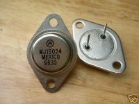
No, those are fake. The real Motorola/Onsemi transistors are perfectly flat underneath.
I believe digikey is a good option, especially that you are in the US. MJ21195/6 is better and cheaper.
clm811 said:I saw some transistors on eBay for a fair price, from "ALLPARTSPIPE".
They claim they are genuine Motorola.
Anyone have experience with this seller?
-chas
No, those are fake. The real Motorola/Onsemi transistors are perfectly flat underneath.
I believe digikey is a good option, especially that you are in the US. MJ21195/6 is better and cheaper.
Nice to know Fairchild Semiconductor is legit. I use a lot of thier products, particularly small signal. Didn't they use to be affiliated with Samsung electronics? I'm thinking there is some sort of relationship there.
Sorry, Charlie
Chas!
Don't trust those fakes- It only costs a few cents more/unit to buy from reputable, domestic sellers. Don't be taken in!
Numerous articles on the rampant sales of counterfeit merchandise from China:
http://www.businessweek.com/magazine/content/05_06/b3919001_mz001.htm
http://www.freerepublic.com/focus/news/2096866/posts
It would be a shame for all your hard DIY work go up in smoke! -Joe
Chas!
Don't trust those fakes- It only costs a few cents more/unit to buy from reputable, domestic sellers. Don't be taken in!
I really wouldn't risk eBay for this sort of thing, esp. not sellers from China which is where the majority of fakes come from.
Numerous articles on the rampant sales of counterfeit merchandise from China:
http://www.businessweek.com/magazine/content/05_06/b3919001_mz001.htm
http://www.freerepublic.com/focus/news/2096866/posts
It would be a shame for all your hard DIY work go up in smoke! -Joe
OnSemi desktop manouveres
Dear All,
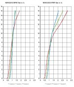
Re: The new(ish) 0302G & 0281G from OnSemi - They are available as both MJW in TO-247 case and NJW in TO-3P. There seem to be 'quite a following building' for these devises...
I have done some spread sheet and other severe desktop manoeuvres in order to have similar Vbe vs. Ic graphs for these OnSemi devises, like the ones published by most far eastern manufactures, to aid the benefit of possible direct comparison.
Please find the graphs attached below in standard PNG format. I have a better detailed version of the file available in open office drawing format as well if you like to request it by mail.
All the best
a1greatdane aka 'Dr' O
Chilli Sound Works
London, UK
Dear All,
Re: The new(ish) 0302G & 0281G from OnSemi - They are available as both MJW in TO-247 case and NJW in TO-3P. There seem to be 'quite a following building' for these devises...
I have done some spread sheet and other severe desktop manoeuvres in order to have similar Vbe vs. Ic graphs for these OnSemi devises, like the ones published by most far eastern manufactures, to aid the benefit of possible direct comparison.
Please find the graphs attached below in standard PNG format. I have a better detailed version of the file available in open office drawing format as well if you like to request it by mail.
All the best
a1greatdane aka 'Dr' O
Chilli Sound Works
London, UK
Attachments
- Status
- Not open for further replies.
- Home
- Amplifiers
- Solid State
- Best hi-volt BJT's for output stage?