Uhm,
In the same time would like to emphasise: I don't want to be a defensor of fast diodes at all costs, only wanted to show that this kind of argumentation provided by Eva, in my opinion, is not sufficient for showing the superiority of the conventional type bridges.
Now, if somebody could point out other aspects clearly in favor of the classical bridges, that would move really forward the debate!
Ciao, George
jneutron:
I said that you were kidding because we are not trying to isolate diode behaviour from test setup influence, what we want to measure is how the diodes behave when they are fed by the distributed inductance/capacitance of the secondary winding of a typical 50/60Hz EI or tororid mains transformer (with the corresponding low di/dt slopes) and when they are feeding electrolytic capacitors through PCB tracks or wires of some lenght and prone to ringing. We were trying to reproducing the real working conditions (sometimes lousy) in which people employs rectifiers in their DIY amplifier projects, and this has not much to do with 250 ps rise times 😀
I said that you were kidding because we are not trying to isolate diode behaviour from test setup influence, what we want to measure is how the diodes behave when they are fed by the distributed inductance/capacitance of the secondary winding of a typical 50/60Hz EI or tororid mains transformer (with the corresponding low di/dt slopes) and when they are feeding electrolytic capacitors through PCB tracks or wires of some lenght and prone to ringing. We were trying to reproducing the real working conditions (sometimes lousy) in which people employs rectifiers in their DIY amplifier projects, and this has not much to do with 250 ps rise times 😀
I took no offense.Eva said:jneutron:
I said that you were kidding because we are not trying to isolate diode behaviour from test setup influence, what we want to measure is how the diodes behave when they are fed by the distributed inductance/capacitance of the secondary winding of a typical 50/60Hz EI or tororid mains transformer (with the corresponding low di/dt slopes) and when they are feeding electrolytic capacitors through PCB tracks or wires of some lenght and prone to ringing. We were trying to reproducing the real working conditions (sometimes lousy) in which people employs rectifiers in their DIY amplifier projects, and this has not much to do with 250 ps rise times 😀
What I am pointing out is the problems measuring what you guys are talking about, with concurrent errors.
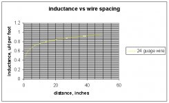
As an example, a 24 guage wire pair exhibits about 1 uH per foot when it's anticurrent mate is 60 inches away.(This spacing chosen to get a reasonable per wire estimate of inductive reactance). For a single current carrying conductor of 24 guage, it is reaonable to assume half a microhenry of reactance.
A diode which will shutoff in 1 usec, and 1.5 amperes (the old jedec spec numbers), that is 1.5 amps per uSec. Using V =L di/dt, the induced voltage across .5 uh is .75 volts, across one inch of 24 guage wire, that voltage error will be 63 millivolts.
If the CVR (as you recommended try) is low enough in value to not disturb the series circuit, say 100 milliohms, the IR drop you are discussing will be on the order of .15 volts give or take.
At 1 amp per microsecond, the error will be 63 / 150, or 42 percent.
A 1 uSec device is a general purpose rectifier.
At 10 amps per uSec, the error becomes 420%.
At 100 amps per uSec (this is typical of a 10 nSec device), the measurement error is 42 times the entity you are trying to measure. Attempts to view this device using a simple resistor, or even using a scope probe with the alligator clip type ground lead, will result in wildly erroneous waveforms of the type that diode manufacturer (onsemi I believe) has provided.
I know how to remove that error very easily. But it is an error that most are unaware of. Discussion of wild transients must be tempered by the fact that they certainly do not exist at the levels that the measurement equipment is reporting.
Cheers, John
edit:math errors, sorry ran outta fingers..
Attachments
John,
I appreciate very much Your intention in pointing out possible caveats!
But I am afraid that momentarily there is some confusion here.
In my diagrams, I have not measured current at all. We were looking for possible voltage spikes induced in the transformer secondary leakage inductance by the diode r.r.current snap. My sniffer is a small 10nF - 2kohm highpass filter, I've been measuring the voltage drop across that 2kohm carbon resistor. So I think the fixture is well damped, no way for MHz resonances.
Then, in the case of measuring current, Your precautions could applie - but:
I was using, as CVR, an ~ 8mm long 50 mOhm sense resistor, from resistor wire. So no way 500nH there, a couple of nH maximum rate.
Then, te change of rate. You talk about 1.5 A / usec rate, while in my actual measurements, because of the slow LRC tank exited, in case of a real setup with ~100uH secondary leakage inductance, 10000 uF filter cap, ~.1 ohm DCR, I got some 8A / 1.5 millisec rate of change, that is, several hundred times lower than that in your example!
Then, while it's true that the alligator ground clips can be a problem, though no current is flowing accross them, I was using a differential setup: two channels with symmetrical probe setup, subtracted.
But the main point here really is the constant presence of the transformer leakage inductance in the order of hundred uH-es, dominating everything in the loop, as pointed out by EVA, correctly?
Ciao, George
Hi,
are we getting close to a conclusion that us DIYers can use?
How do we measure that leakage inductance of a toroid?
Then, how do we calculate the component values needed for a useful (not useless) snubber?
are we getting close to a conclusion that us DIYers can use?
How do we measure that leakage inductance of a toroid?
Then, how do we calculate the component values needed for a useful (not useless) snubber?
Eva said:We are working at approx. 1A per 100 microseconds.
While the surrounding circuitry and drive currents are indeed doing such, the diode is under no such constraint.
When a diode is forced to carry current in the reverse direction, when the carrier supply collapses either by sweep or recombination with dislocation sites (gold or platinum), the current will collapse at the diode's desire, not the circuit.
If the circuit has high inductance, as is the case for the supplies we are speaking of, it's reaction will be to very rapidly sweep the depletion zone of the silicon, charging the internal capacitance very swiftly. Note that the capacitance continues to fall as the reverse voltage increases.
What I am pointing out is that while you believe you are working in the 1 amp per microsecond realm, the diode is not.
Cheers, John
Joseph K said:John,
I appreciate very much Your intention in pointing out possible caveats!
But I am afraid that momentarily there is some confusion here.
In my diagrams, I have not measured current at all. We were looking for possible voltage spikes induced in the transformer secondary leakage inductance by the diode r.r.current snap. My sniffer is a small 10nF - 2kohm highpass filter, I've been measuring the voltage drop across that 2kohm carbon resistor. So I think the fixture is well damped, no way for MHz resonances.
Then, in the case of measuring current, Your precautions could applie - but:
I was using, as CVR, an ~ 8mm long 50 mOhm sense resistor, from resistor wire. So no way 500nH there, a couple of nH maximum rate.
Then, te change of rate. You talk about 1.5 A / usec rate, while in my actual measurements, because of the slow LRC tank exited, in case of a real setup with ~100uH secondary leakage inductance, 10000 uF filter cap, ~.1 ohm DCR, I got some 8A / 1.5 millisec rate of change, that is, several hundred times lower than that in your example!
Then, while it's true that the alligator ground clips can be a problem, though no current is flowing accross them, I was using a differential setup: two channels with symmetrical probe setup, subtracted.
But the main point here really is the constant presence of the transformer leakage inductance in the order of hundred uH-es, dominating everything in the loop, as pointed out by EVA, correctly?
Ciao, George
Ah, last math error of mine in post..forgot to convert from 500 nH of a foot, to 1 inch CVR. 42 nH for one inch. At 8 mm, that'd be 13 nH.
So let's have an abrupt I dot of 1.5 amperes/1 uSec.
.013 uH times 1.5 is 19.5 millivolts.
That is for a standard recovery device. BTW, that is the timeframe for the device to arrive at zero conduction, and does not represent the rate that it "zones out". Abrupt recovery devices are very bad in this respect. So I use the device spec'd number just for reference, with the caveat the real devices will transit from reverse conduction to zero at approximately 10 times the rate. My estimates are lowballs.
100 Nsec devices...195 millivolts
10 nSec, 2 volts.
IF the 10 nano device actually recovers in 1 nSec, 20 volts?? That is the voltage response on your 8mm long resistor, 50 milliohm resistor.. Your resistor design would not be acceptable for use in a TRR fixture as a result of it's inductive storage. Yes, it is low, no it cannot accurately distinguish the current change in a fast or medium fast diode.
The one or half amp signal in reverse direction is being viewed as a 50 millivolt signal, but yet the resistor will generate 4 to 400 times that depending on the snap characteristics of the silicon.
As I said, how does one distinguish the characteristics of the silicon independently of the cvr?
Personally, I would be less apt to recommend the selection of a diode based on it's recovery characteristics if all I had to go on was waveforms and writeups based on those waveforms where the test conditions were incapable of discerning real differences. If you really want to identify the issue of diode selection vs sound, this is not the best place to look. I note that both of you are also looking at the other circuit element waveforms, and are doing so quite well. I have been very happy to read both your's and Eve's posts.
Using a differential probe setup does not remove the pickup inductance. You must consider the physical signal path loop.
I have found that those little probe tip females, the kind that come with the hp or tek probes, are the best, but the physical size of your resistor does not allow taking advantage of that.
This is why I said I can detail a resistor which does not suffer the issue I speak of.
Cheers, John
Edit: Joseph, I just remembered that you were the one I had the braid over capacitor discussion with...
Your resistor suffers the exact same thing..the external inductance..
If you take 10, 1 ohm resistors and parallel them to form a cylinder..have the circuit current flow through those. To measure the current through this resistor, run a wire through it on axis, use the scope from this wire to the tie point opposite the wire connection. That removes the scope wire from all collapsing magnetic fields. This is exactly what I had mentioned as possibly sending to you for measurement on the analyzer..
John,
You are putting me under the torque...
I'm afraid I have to retire now, and will not be able to continue with that damn GPRS connection, but one point, just to underline my confusion:
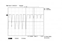
Here, in the scope shot below, I was using that 50 mOhm CVR, and one can see the ~2A current pulses[100mV peak in the pic], or the ~8A current pulses[400mV peak], the 2A ones having a half width of ~ 1.5mSec, the 8A pulses are having ~3msec half width.
The current is changing, because I was testing the system response to a "step" in the load current.
Evrything is inverted because it came like this in the process off subtracting, the zero line is obviously on top.
What, in fact, I was NOT able to see, never, are the "they should be there" fast current glitches at the diode turn off moment.. The rectifiers used here were actually MBR 760s, but I saw the same with MUR860, which are ~ 60nsec Trr devices, so should have shown ~ 400mV peak?
These glitches were only visible while looking at the tension of transformer secondary, and only with conventional rectifiers, nothing with the fast rectifiers...
Ciao, George
You are putting me under the torque...
I'm afraid I have to retire now, and will not be able to continue with that damn GPRS connection, but one point, just to underline my confusion:
Here, in the scope shot below, I was using that 50 mOhm CVR, and one can see the ~2A current pulses[100mV peak in the pic], or the ~8A current pulses[400mV peak], the 2A ones having a half width of ~ 1.5mSec, the 8A pulses are having ~3msec half width.
The current is changing, because I was testing the system response to a "step" in the load current.
Evrything is inverted because it came like this in the process off subtracting, the zero line is obviously on top.
What, in fact, I was NOT able to see, never, are the "they should be there" fast current glitches at the diode turn off moment.. The rectifiers used here were actually MBR 760s, but I saw the same with MUR860, which are ~ 60nsec Trr devices, so should have shown ~ 400mV peak?
These glitches were only visible while looking at the tension of transformer secondary, and only with conventional rectifiers, nothing with the fast rectifiers...
Ciao, George
Attachments
Joseph K said:What, in fact, I was NOT able to see, never, are the "they should be there" fast current glitches at the diode turn off moment.. The rectifiers used here were actually MBR 760s, but I saw the same with MUR860, which are ~ 60nsec Trr devices, so should have shown ~ 400mV peak?
These glitches were only visible while looking at the tension of transformer secondary, and only with conventional rectifiers, nothing with the fast rectifiers...
Ciao, George
At that time base, I don't think you can see any recovery transients. Actually, I believe a lot of the high end talk of transient stuff is just, um, interesting creative dialogue.
Looking at the voltages is really the way to go in the supply.
For audio sound, don't look in the supply. Look at the induction of currents elsewhere, like ground.
Cheers, John
John,
That is a very valid point!
Ciao, George
For audio sound, don't look in the supply. Look at the induction of currents elsewhere, like ground.
That is a very valid point!
Ciao, George
AndrewT said:How do we measure that leakage inductance of a toroid?
Then, how do we calculate the component values needed for a useful (not useless) snubber?
Short the primary leads together and measure the inductance of the secondary -- you can use the simple (and acurate) bridge method discussed by Steber: http://www.arrl.org/qex/2005/Steber.pdf
It is also helpful to know the winding coupling capacitance, and DC Resistance of the primary and secondary -- you can also measure this with a bridge.
There are a number of papers on calculation of snubber values -- and different types of snubbers for the application -- one often cited paper is by Hagerman "Optimum Snubbers" -- easy to find on the web.
Jackinnj,
should the primary or the secondary be shorted ? Not arguing, just thought I had heard/read otherwise somewhere so I thought I'd confirm.
I used Speaker Workshop to measure the inductance.
should the primary or the secondary be shorted ? Not arguing, just thought I had heard/read otherwise somewhere so I thought I'd confirm.
I used Speaker Workshop to measure the inductance.
Elso,
It's good that You have reported that thread here, thanks!
Though if You intended to say "we are going in circles; everthing had been told before" then I say yes, we are going in circles -- though just the post 8 of that thread [by SY] justifies the new efforts here.. 😀
Ciao, George
It's good that You have reported that thread here, thanks!
Though if You intended to say "we are going in circles; everthing had been told before" then I say yes, we are going in circles -- though just the post 8 of that thread [by SY] justifies the new efforts here.. 😀
Ciao, George
forr said:
Hi Poobah,
In an other thread, Quasi suggested you needed a hair-cut. I've seen you have been to the hair dresser. But not for the intended aim.
regards ~~~~ Forr
§§§
....and it seems you've taken up smoking !
Re: Diodes
Hmm..
The links in the first post are nice. It's good to see that what I recall from previous work experience is still consistent with what they write. It is bad to see that they have not advanced a bit in TRR testing over the last 20 years.
Gensemi link was dead, though.
Any manu's actually write about using fast diodes in line supplies, or are all the manu tech papers out there still all about switching stuff and transient V-I losses (losses during switching)?
Cheers, John
Elso Kwak said:
Hmm..
The links in the first post are nice. It's good to see that what I recall from previous work experience is still consistent with what they write. It is bad to see that they have not advanced a bit in TRR testing over the last 20 years.
Gensemi link was dead, though.
Any manu's actually write about using fast diodes in line supplies, or are all the manu tech papers out there still all about switching stuff and transient V-I losses (losses during switching)?
Cheers, John
Hi,
sorry for bringing up this old thread.
Does anybody have suggestions for fast switching, smooth recovery diodes to replace 1N4007s in a preamp? (and a source for them)
These "Hexfred" diodes are quite interesting: HFA15TB60PBF pdf, HFA15TB60PBF description, HFA15TB60PBF datasheets, HFA15TB60PBF view ::: ALLDATASHEET :::
... albeit they are guite large and expensive and I would like to find a diode with comparable specs (max forward current does not need to exceed 1A) but with smaller size, maybe regular "axial" kind of diode since 1N4007s are too.
Regards,
Legis
Last edited:
Hi guys, Vector plane makes a good point, in all the stuff I work on, audio gear and test gear, all the power supplies use...1N400x. That said, HexFred's or Schottky's is way more sexy then a plain ole diode. For a few bucks, who cares, I'll use the over engineered fancy devices and enjoy the result weather or nor I can hear it...or even measure it. Its a fun...hobby. Thanks all.
- Status
- Not open for further replies.
- Home
- Amplifiers
- Power Supplies
- Best diodes for generic power supply