High speed diodes thread
There was a thread in the past about high speed diodes, started by Fred dieckmann.......
Most was said there.
😎
There was a thread in the past about high speed diodes, started by Fred dieckmann.......
Most was said there.
😎
Can't anybody build a nice test setup allowing to measure reverse-recovery current and voltage spikes for various transformer and diode types???
I did it for conventional diodes and published the measurements and real oscilloscope waveforms. I also showed how to damp the spikes associated to these diodes until they were barely measurable. However, I'm busy now with an urgent project.
Anyone?
I did it for conventional diodes and published the measurements and real oscilloscope waveforms. I also showed how to damp the spikes associated to these diodes until they were barely measurable. However, I'm busy now with an urgent project.
Anyone?
Hi EVA
--- did it for conventional diodes and published the measurements and real oscilloscope waveforms. I also showed how to damp the spikes associated to these diodes until they were barely measurable.---
Is there a link, please ?
~~~ Forr
§§§
--- did it for conventional diodes and published the measurements and real oscilloscope waveforms. I also showed how to damp the spikes associated to these diodes until they were barely measurable.---
Is there a link, please ?
~~~ Forr
§§§
Check this thread. I start posting in page 6 (I think) and the interesting stuff starts from page 7. Other people also attached waveforms, but as theirs came from simulations and simulators doesn't model diode reverse recovery properly at all, they had little to do with reality.
http://www.diyaudio.com/forums/showthread.php?s=&threadid=66542
Note that diodes suffer an abrupt impedance change just when they stop conducting, and when they are connected in series with an inductor in which some current is flowing, a voltage spike is produced that excites any possible HF resonant modes of the entire system. Placing a low HF impedance in paralell with the diode damps the voltage spike, and may also damp system resonances if the right component values are chosen. Don't expect any simulator to model that properly, it has to be measured with oscilloscope and real components (that's the dirty work nobody wants to do).
Eva said:Placing a low HF impedance in paralell with the diode damps the voltage spike, and may also damp system resonances if the right component values are chosen. Don't expect any simulator to model that properly, it has to be measured with oscilloscope and real components (that's the dirty work nobody wants to do).
Doesn't the junction capacitance of a diode changes through the conduction cycle?
It is a lot of work, tedium, and it must be painstakingly acurate.
Capacitance of a diode changes with everything, including temperature, current and voltage (forward or reverse). However, I think that capacitance is of little interest when the diode is forward biased and conducting, as it's effectively shunted by the own diode and all the possible HF resonance excitation energy would be dissipated in the first cycle of HF excitation.
Actually Jack, the cap value is not super critical... just get the decimal point in the right place and you can make a vast improvement...
😉
😉
Cap value is not super critical for spike supression, but this added capacitance is the one that will resonate with transformer leakage inductance. This makes the value a bit more critical. Also, a series resistor will help to avoid resonance but will reduce spike supression performance, that's why I employed a capacitor and a RC in paralell with it.
This graph has no useful information for us. Note that the current downslope is 1A per 10 nanoseconds (100A/us standard test for ultrafast diodes) and the thing rings at several dozen Mhz.
Reverse recovery behaviour is entirely dependent on this current downslope (as charge is removed from the junction slower or faster and the diode stops conducting only some time after all charge has been removed), that for 50/60Hz rectification applications is more like 1A per 100 microseconds. I doubt that the own manufacturer has even measured their diodes in these working conditions. I will do it and post the results when I find some spare time to prepare the experiment.
Note that several graphs from diode datasheets show that reverse recovery time increases substantially as current downslope is reduced, so we may easily find out that ultrafast diodes acually behave much like standard diodes when current downslopes are as low as 1A per 100us.
Eva,
RANT MODE ON
here:
First part
continued here
I think one could have found almost everything - measurements, explanations, formulas and graphs - if one would have made that small effort of searching the forum for previous art.. 😀
And yes, diode capacity counts, and it is visible from the measurements. What is also visible is the clear superiority of the MUR type fast & smooth recovery diodes, over the classic rectifier bridges, in this particular reference [reverse recovery spikes].
And yes, this was a sidenote responding to You fom that other thread.
And also the formulas and methods were shown if someone wants to use C // RC damping of those spikes, instead of completely avoiding them.
RANT MODE OFF
Otherways I think we agree in most of the points.. 🙂
Ciao, George
RANT MODE ON
Can't anybody build a nice test setup allowing to measure reverse-recovery current and voltage spikes for various transformer and diode types???
Anyone?
here:
First part
continued here
I think one could have found almost everything - measurements, explanations, formulas and graphs - if one would have made that small effort of searching the forum for previous art.. 😀
And yes, diode capacity counts, and it is visible from the measurements. What is also visible is the clear superiority of the MUR type fast & smooth recovery diodes, over the classic rectifier bridges, in this particular reference [reverse recovery spikes].
And yes, this was a sidenote responding to You fom that other thread.
And also the formulas and methods were shown if someone wants to use C // RC damping of those spikes, instead of completely avoiding them.
RANT MODE OFF
Otherways I think we agree in most of the points.. 🙂
Ciao, George
JosephK -- yeah, that was me -- but instead of using the real world transformer (for the moment) I would now change the procedure to just use several inductors 10uH, 33uH, 50uH, 100uH etc. in series with the various diodes. For the moment "assume away" the coupling coefficient inefficiency of the transformer and interwinding capacitance, resistances.
Like any other experiment, at first you want to separate out the independent variables one at a time, then see if you can predict the interdependencies from first principles.
Like any other experiment, at first you want to separate out the independent variables one at a time, then see if you can predict the interdependencies from first principles.
Good work Joseph.
But your oscilloscope pictures show that ultrafast and schottky diodes take much longer to stop conducting when they are driven with very low di/dt and also produce a turn-off spike (smaller) and some ringing (of higher frequency so more likely to be radiated, and that should be damped with a suitable RC anyway).
On the other hand, my measurements contrasted to yours show that a classic KBPC25 diode bridge with just a suitable C and a RC across the AC terminals does not produce any spike or ringing and behaves better than MUR and MBR diodes when they are used without anything else.
Finally, you also found out that placing 100nF capacitors across electrolytics actually worsens any supply ringing problem because dissimilar capacitors resonate mutually when paralelled. That's something that I'm always emphasizing, because most people believe they are doing the right thing when the paralell dissimilar capacitors (sometimes three or four!!).
p.s.: If you do similar measurements again, include a small shunt resistor in order to measure diode current. Here is where the spike will be best observed.
I'm afraid I haven't dealt with reverse recovery speeds and fixtures that are as slow as that graph, but I believe that ringing is simply fixture inadequacies.
Get the fixture to settle in 200 or so picoseconds, then you'll get a clearer picture of what's going on.
Cheers, John
If you wish to monitor the current, you have to balance the CVR symmetrically, to eliminate I dot errors. An easy task with some simple matched carbons. (don't use precision metal films, they're spirally trimmed..
Eva said:He should be kidding 🙂
Should be, but am not.
As a test engineer for the largest manufacturer of diodes on the planet (4 million units per day at the time), One of my tasks was measurement of TRR, both for existing product, and for newer higher speed R and D. In that capacity, I developed a TRR fixture capable of measuring the snap recovery of a diode with sufficient bandwidth to show a square wave with 250 picosecond rise times. This of course, required the use of microwave power resistors (BeO) and the layout from "heck".
I discovered then (1981) a signal generator called a Tek type 109 (at the time it was over 20 years old) which produced 250 pico rise/350 pico fall times. A little known attribute of mercury wetted reeds is their amazing rate of current change during make or break.
My fixture allowed the diffusion Phd's to see exactly what the diode was doing in the sub nano regime, and gave them feedback for diffusion profile modifications.
Seeing the waveforms being presented on these posts remind me of the horribly speed challenged TRR fixtures I have seen in the intervening years, and the incorrect assumptions resulting from the inadequacies of the test methods and materials. Also, the fundamental errors which we (I include myself) have committed in trying to measure these speeds in low Z circuitry.
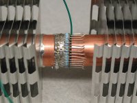
One of the easier things to remove, is the inductance of the current viewing resistor. It is actually rather trivial to make one which theoretically goes below 60 picohenries. I made one, pic attached. I must note that I have tried to measure the inductance of this beast, but have not been able to acheive a reliable measure at the 60 pHenry level, I am only able to get the measurement down to 250 picohenry maximum. (this inability stems from the current path taken as it spreads out to the ring of resistors, I cannot physically remove that.)
Anyone interested in making a simpler one that will be good to the single digit nanohenry level, I'll describe it. It would take only 2 or 3 matched 1/4 or 1/2 watt carbons to make a simple one which outperforms even the caddock ceramic types by an order of magnitude.
(I have much experience in this area, having been bit in the hindmost on many occasions)
As the waveforms are such a confusing mess, it it very difficult to figure out which is due to the diode, which the surrounding circuitry, and which the result of measurement error as a result of inductive coupling and inductive reactance. This is why I said get the stuff to settle in 200 pico or less, that way it is much easier to understand the waveforms without wondering how much of it is related to the measurement technique. I would be happy to evaluate and put my two cents worth in if pictures of the setup including scope probe were presented. There is a very small possibility that my experience could be of some use. Ok, maybe a small possibility, but I can dream..😉
Cheers, John
Edit: yah, the right side is not soldered, this is a pic of the incomplete one. I did not have a good pic of the finished which shows the detail of the resistors.
This configuration is that of a 36 pole magnet, and the external field drops off as 1/R37, internal as1/R35 . Another way of looking at it is paralleling of 36 inductors of small value, in an antiparallel configuration.
Oh, forgot..I don't work at that diode company now. That was back in '81 to '84.
Attachments
That look's an aweful lot like a space modulator. I have had to build IGBT snubbers that were as messy.
😀
😀
What is wrong with you...??😀poobah said:That look's an aweful lot like a space modulator. I have had to build IGBT snubbers that were as messy.
😀
Given your Avatar, I was sure you'd say it looked like a tie fighter😕😕 You're under your game there..
Actually, I figgered it looks more like a space heater, what with the fins and all.
It's amazin what ya can do with a section of slantfin from Home depot and some resistors from Digikey. (my first test load resistor got overheated and melted the solder, it was on a 1/2 inch diameter tubeset, with no heat sink fins...using the slantfin allows more dissipation.
My next config will be a symmetrical block style, and I'll epoxy encapsulate it with a CPU cooler as the base of the structure. That'll get me into the several hundred watt RMS regime without melting the solder again.
Cheers, John
Eva, all -
Bah, yesterday I've just lost a 500 page answer to Eva bacuse of my stupid gprs home connection....
John, are You talking about my graphs or about that one shown by Jackinnj in post49?
Because I can only talk about my things. Yes, You are right in that I was not conducting a checkup for my test fixture - I can still do that. But: the observed resonance in my case, at around 400 kHz, is way too low a frequency to be a result of a parasitic resonance due to fixture / probe lead inductance.. while Your observation is totally in place as regards the pushed to the edge test environment in your case, in this simple case of ours with ~100 uH leakage inductance of the home transformer's secondary, and the several nF stray capacitances in play, the measured resonance seems to be on spot. Then, I could shift it by will by adding extra capacitance, and the results were in accordance with the calculations. Also I was able to note the resonance shift due to diode reverse junction capacitance, [in case of different diodes] and the measured offset was in accordance with the datasheet values controlled later..
Eva,
I think we are in a gross agreement in almost all but this:
I would like to point out again, that in accordance with what was written here, in post 545, the fast diodes does not produce at all a spike, but rather a "step" response, with a step level in accordance with their forward voltage drop! Now, this step response, of about .5 V magnitude in it's really fast part, is riding on the whale-back of the 50 Hz sinusoidal. So the already much smaller high frequency energy content [with respect to the ten volts order real spike in case of a slow bridge rectifier] is subject of an even further LP filter effect because of the "hold"-like function with 50Hz fundamental...
Note also that this "step" exists the same way even in case of normal diodes, only is hardly visible because of the high level of reverse snap and ringing!!
Then, while the reverse snap with slow diodes is proportional to the original forward current, so provides for a nice AM modulation with the audio signal, with spectral components up to the MHz range, with the fast diodes this mechanism is totally absent.
Then, while it's true that one can slow down & dampen the spike and ringing with the appropriate values of snubber components,
how many real applications have You seen done that properly?
Finally, yes, I know about the recharge current spikes refilling te reservoir caps, have played with measurements and simulations, and got some [at least for me] unexpected results..
http://www.diyaudio.com/forums/showthread.php?postid=603560#post603560
ciao, George
Bah, yesterday I've just lost a 500 page answer to Eva bacuse of my stupid gprs home connection....
John, are You talking about my graphs or about that one shown by Jackinnj in post49?
Because I can only talk about my things. Yes, You are right in that I was not conducting a checkup for my test fixture - I can still do that. But: the observed resonance in my case, at around 400 kHz, is way too low a frequency to be a result of a parasitic resonance due to fixture / probe lead inductance.. while Your observation is totally in place as regards the pushed to the edge test environment in your case, in this simple case of ours with ~100 uH leakage inductance of the home transformer's secondary, and the several nF stray capacitances in play, the measured resonance seems to be on spot. Then, I could shift it by will by adding extra capacitance, and the results were in accordance with the calculations. Also I was able to note the resonance shift due to diode reverse junction capacitance, [in case of different diodes] and the measured offset was in accordance with the datasheet values controlled later..
Eva,
I think we are in a gross agreement in almost all but this:
that ultrafast and schottky diodes... also produce a turn-off spike (smaller)
I would like to point out again, that in accordance with what was written here, in post 545, the fast diodes does not produce at all a spike, but rather a "step" response, with a step level in accordance with their forward voltage drop! Now, this step response, of about .5 V magnitude in it's really fast part, is riding on the whale-back of the 50 Hz sinusoidal. So the already much smaller high frequency energy content [with respect to the ten volts order real spike in case of a slow bridge rectifier] is subject of an even further LP filter effect because of the "hold"-like function with 50Hz fundamental...
Note also that this "step" exists the same way even in case of normal diodes, only is hardly visible because of the high level of reverse snap and ringing!!
Then, while the reverse snap with slow diodes is proportional to the original forward current, so provides for a nice AM modulation with the audio signal, with spectral components up to the MHz range, with the fast diodes this mechanism is totally absent.
Then, while it's true that one can slow down & dampen the spike and ringing with the appropriate values of snubber components,
how many real applications have You seen done that properly?
Finally, yes, I know about the recharge current spikes refilling te reservoir caps, have played with measurements and simulations, and got some [at least for me] unexpected results..
http://www.diyaudio.com/forums/showthread.php?postid=603560#post603560
ciao, George
- Status
- Not open for further replies.
- Home
- Amplifiers
- Power Supplies
- Best diodes for generic power supply