I believe Ivar (tubo) still has inventory of Onetics OPTs. At least he did in July 2020. Check this link for more details...
Onetics output transformer liquidation SALE
Take a look at the OP of that thread. All sold except that one 2A3 pair, which I eventually bought.
I'm not Andy, but Dear "What Do We Call You?", itsikhefez doesn't sound like an easy handle,
I'd say better get with the program and just do it!
Martin Seddon (Azura Horn), in OZ, suggested exactly this OP from the 300B Tables for a DC coupled Monkey Amp 6, 7, 8 years ago on the JoeList. That one is in my queue and requires a 200H choke which I've since sourced.
They're not highlighted in the table, but do note the H2 and H3 levels.
I'm sure Andy would say "EXPERIMENT!"
Very Best,
Robert
itsikhefitz,
You picked the operating conditions that bring the lowest distortion and highest primary impedance on that whole chart.
A clean 6.2 Watts is very good, and should be better than a little more power that has a lot higher distortion.
And the damping factor of your selected operating condition is the best.
Have fun building, and have fun listening.
Robert, my handle is simply my full name !
Thank you both for the motivation!
I noticed the H2 and H3. Those are in dB below the fundamental, correct? If so, that would
make them the lowest distortion point in the chart as 6A3sUMMER points out.
I've been running an EL84 SE amp with my Klipsch speakers for the past few months. The output is 3.8W with about 3% THD (measured with ARTA) and sounds really good... so I think 6.2W of 300B will be more than enough!
BTW, received this nice package from Rossville, GA this week.... but I don't think they will go into an amp any time soon. The boxes will likely remain sealed, stored somewhere safe.
Attachments
BTW, received this nice package from Rossville, GA this week.... but I don't think they will go into an amp any time soon. The boxes will likely remain sealed, stored somewhere safe.
Are they new manufacture? Just curious with the RoHS certification.. Just googled and yes - nice.. wonders when the 2a3 production will start too (pure speculation!)
Last edited:
Yes these were manufactured this year and purchased directly from W.E.
QR code is another hint 🙂
QR code is another hint 🙂
I noticed the H2 and H3. Those are in dB below the fundamental, correct? If so, that would
make them the lowest distortion point in the chart as 6A3sUMMER points out
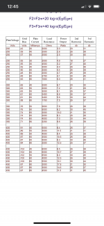
itsikhefez: There are other operating points that are similarly low distortion. The output transformers primary impedance appears to be the most significant factor in attaining low distortion. If you have a chance, check out the full chart. I remember a couple of pages of OP charts, but didn’t find it just now in a quick search. Have a look at this more full chart I found. While it is a small difference, the lowest distortion is on the last OP on the list, which is into a 5K OPT primary, and puts out 11.5 Watts!
Attachments
Last edited:
The output transformers primary impedance appears to be the most significant factor in attaining low distortion.
i wonder about this. What part does the gap play? An OPT gapped for 50mA isn't going to be the same as one gapped for 80mA. The inductance would change. I haven't seen any charts that take that into consideration. Can anyone enlighten me here?
300B Power, H2 and H3 vs Primary Z For Various Ia
If you look to http://www.tubebooks.org/tubedata/we300a_b.pdf
on Page 7 there are plots of output power as well as H2 and H3 versus primary Z for four different values of plate current from 30 to 80 mA that show increasing plate current to have a strong affect on reducing distortion.
RC
If you look to http://www.tubebooks.org/tubedata/we300a_b.pdf
on Page 7 there are plots of output power as well as H2 and H3 versus primary Z for four different values of plate current from 30 to 80 mA that show increasing plate current to have a strong affect on reducing distortion.
RC

If you look to http://www.tubebooks.org/tubedata/we300a_b.pdf
on Page 7 there are plots of output power as well as H2 and H3 versus primary Z for four different values of plate current from 30 to 80 mA that show increasing plate current to have a strong affect on reducing distortion.
RC
The sweet spot for current looks like 60mA which is what they recommend. But unless I've missed something, this doesn't indicate what the OPT is actually gapped for. Am I right in thinking these are theoretical figures, and not derived from actual tests on OPTs?
The sweet spot for current looks like 60mA which is what they recommend. But unless I've missed something, this doesn't indicate what the OPT is actually gapped for. Am I right in thinking these are theoretical figures, and not derived from actual tests on OPTs?
andyjevans: if you look at the last three rows in the chart I posted above, there are three operating points at 80 mA with OPT primary impedances increasing as you move towards the bottom. Distortion and output power drop as primary impedance increases. This is at a high 80 mA. There is a substantial increase in distortion as impedance drops. In general, lower distortion is associated with higher primary impedance. Inductance is certainly relevant, but it’s going to vary greatly from OPT to OPT, and is more about OPT quality than anything else. A chart similar to the one I posted above that used inductance would be interesting, but not as useable as a reference. I think it would be best to use the WE chart to pick an OP, and then pick an OPT based on other quality factors and your budget.
andyjevans,
I do not think the gap size is the only factor to how a SE transformer sounds, unless all the other transformer parameters are the same.
Choose a Gap dimension (distance from Is to Es), use that as a fixed standard for this thought process.
1. Choose a Lamination stack size (volume).
Choose a number of turns in the primary, and set the secondary turns according to the desired impedance ratio (5K to 8 Ohms is 25 to 1 turns ratio).
Choose a quiescent current that does not saturate the core, even when the peak current doubles that current.
2. Now, double the Lamination size (volume)
Use the same air gap dimension (Is to Es spacing)
Use the same number of turns for the primary and secondary, the length of a turn increases, so use a larger wire size to get the same DCRs of the primary and secondary.
Use a quiescent current that does not saturate the core, even when the peak current doubles that current.
3. Compare
Transformer #2 will have more inductance (even though the air gap spacing of Is and Es is the same as transformer #1).
Transformer #2 will have less low frequency distortion at the max unsaturated low frequency power of transformer #1 (even though the air gap spacing of Is and Es is the same).
Transformers #2 and #1 will probably have different high frequency responses and phase shifts; they will have different distributed capacitance, and different leakage inductance (leakage reactance).
Even if the low frequency signal level is moderate, and is far below saturation of either transformer #1 or #2, then . . .
transformer #2 which has more inductance, will produce less low frequency distortion (the 300B plate curves, versus the impedance of inductance at low frequency causes a steeper load line slope from primary #1 (more accurately, a steeper elliptical load line from primary #1).
Low impedance load (resistive, reactive, or both) on a SE tube amp creates more 2nd harmonic distortion.
4. If you have a fixed lamination size, turns, etc.; then yes, changing the air gap thickness will change inductance, max quiescent current, max signal current at low frequency, frequency response, etc.
Last edited:
Another point about the WE charts.
Distortion is calculated by using the plate curves, and a purely resistive loadline.
Real transformers are not pure resistive loads.
Power out is calculated into a purely resistive load.
A transformer has insertion loss, so the power you get at a listed impedance and distortion levels will not be as good.
Your Mileage Will Vary.
Excellent post!! Thanks for that. All the information is relevant and well expressed.
My point related to your point #4. What if the size and construction of the transformer was kept constant and just the gap varied? As you say, that would change the inductance and change the response. I would expect a higher inductance in itself to show lower distortion, but this all relates back to current and operating point.
As an example I have a SE LL1664 at 3K and 70mA into 8 ohms which doesn't sound as good with a 300b output as a LL1682 at 5K and 50mA into 5 ohms. Speaker being a single unit Alpair 10M, nominally 8 ohms. Here we have 2 relevant factors - the turns ratio and the gap. I'm assuming a current of 70mA for the LL1664 and 50mA for the LL1682. So which is doing what? The WE figures don't explain this comparison and again, I'm guessing the data is theoretical and not measured directly from OPTs specifically gapped for the quoted current in the data.
.
Last edited:
In my case, I already have the LL1663/50mA and was looking for the optimal operating condition for that specific OPT, so I'm less flexible in choosing any one I want.
I am locked into 5K primary and theoretically up to 50mA bias.
As concluded before, 350V, 5K and 50mA seems to be a good choice and I will be using that with my Tubelab PCB (that I also already have).
That said, I was curious if it is OK to try 60mA, and sent an email to Lundahl. This was the reply:
Anyhow, the plan was to measure THD and FR for both 50ma and 60ma with ARTA.
I am locked into 5K primary and theoretically up to 50mA bias.
As concluded before, 350V, 5K and 50mA seems to be a good choice and I will be using that with my Tubelab PCB (that I also already have).
That said, I was curious if it is OK to try 60mA, and sent an email to Lundahl. This was the reply:
Yes, you can run the 300B at 60mA with an LL1663/50mA
You will get 20% less headroom compared to run it at 50mA, but this is not a problem unless you are concerned with max power.
Anyhow, the plan was to measure THD and FR for both 50ma and 60ma with ARTA.
andyjevans,
I do not think the gap size is the only factor to how a SE transformer sounds, unless all the other transformer parameters are the same.
Choose a Gap dimension (distance from Is to Es), use that as a fixed standard for this thought process.
1. Choose a Lamination stack size (volume).
Choose a number of turns in the primary, and set the secondary turns according to the desired impedance ratio (5K to 8 Ohms is 25 to 1 turns ratio).
Choose a quiescent current that does not saturate the core, even when the peak current doubles that current.
2. Now, double the Lamination size (volume)
Use the same air gap dimension (Is to Es spacing)
Use the same number of turns for the primary and secondary, the length of a turn increases, so use a larger wire size to get the same DCRs of the primary and secondary.
Use a quiescent current that does not saturate the core, even when the peak current doubles that current.
3. Compare
Transformer #2 will have more inductance (even though the air gap spacing of Is and Es is the same as transformer #1).
Transformer #2 will have less low frequency distortion at the max unsaturated low frequency power of transformer #1 (even though the air gap spacing of Is and Es is the same).
Transformers #2 and #1 will probably have different high frequency responses and phase shifts; they will have different distributed capacitance, and different leakage inductance (leakage reactance).
Even if the low frequency signal level is moderate, and is far below saturation of either transformer #1 or #2, then . . .
transformer #2 which has more inductance, will produce less low frequency distortion (the 300B plate curves, versus the impedance of inductance at low frequency causes a steeper load line slope from primary #1 (more accurately, a steeper elliptical load line from primary #1).
Low impedance load (resistive, reactive, or both) on a SE tube amp creates more 2nd harmonic distortion.
4. If you have a fixed lamination size, turns, etc.; then yes, changing the air gap thickness will change inductance, max quiescent current, max signal current at low frequency, frequency response, etc.
ad 1. You start with good winding geometry, so use all available winding space.
ad 2. Now you have a problem: doubling the lamination size will not change the available winding space, so there is no room for thicker wire in order to keep DCR's the same 🙁😀
In other words: to do this experiment you must change from let's say EI 96 to EI 120.
Better still to work with c-cores, but US winders seem to neglect the superiority of c-cores (Dave Slagle the only positive exception...).
This thread is about the "best 300B OPT", so check which type of core is used by winders like Tango, Monolith Magnetics, Tribute, Alexander (member 50AE), Lundahl...
Last edited:
I was curious if it is OK to try 60mA, and sent an email to Lundahl. This was the reply:
Very interesting! That's good information. Let us know what differences you get with 50mA and 60mA. Your operating point looks fine and you should get a really good result with a 300b. My LL1682 at 5K/50mA sounds really nice.
You cannot specify DC current capability that tight!
When Lundahl states that putting 60mA through a transformer specified for 50mA costs 20% of headroom, every experienced transformer winder will know that the 50mA specification is already too much on the edge.
There must be more headroom available.
DCR's of LL1664 and LL1682 are too high; these transformers should not be the subject of discussion in this thread.
You cannot specify DC current capability that tight!
When Lundahl states that putting 60mA through a transformer specified for 50mA costs 20% of headroom, every experienced transformer winder will know that the 50mA specification is already too much on the edge.
There must be more headroom available. DCR's of LL1664 and LL1682 are too high; these transformers should not be the subject of discussion in this thread.
Thanks for that. I'm not going to defend the LL1664, but I do really like the LL1682 with a 300b and I will defend that particular OPT. I do agree that Lundahl transformers are a mixed bag. Some good, others ho-hum. There are indeed better transformers out there to discuss, as you say.
If you look at Fig 2.3 here:
BH Curve Relationship | Magnetization Characteristic | Equivalent Circuit
you'll see how idling (bias) current needs to sit on a magnetization curve. Higher idling current (further to the right on the curve) requires that the operating signal swing approach saturation sooner. Simultaneously the output valve's grid approaches zero bias sooner, because it began from a closer idling point.
Changing the air gap in otherwise identical transformers changes the slope of the B/H curve and the sharpness of the knee into saturation. Idling current changes the zero signal position on the curve.
All good fortune,
Chris
HI AndyThanks for that. I'm not going to defend the LL1664, but I do really like the LL1682 with a 300b and I will defend that particular OPT. I do agree that Lundahl transformers are a mixed bag. Some good, others ho-hum. There are indeed better transformers out there to discuss, as you say.
the lundhal officially 300B is LL1623 is 1kg more and sound good with good price vs Holand amorphous iron
HI Andy
the lundhal officially 300B is LL1623 is 1kg more and sound good with good price vs Holand amorphous iron
I had a LL1623 and it is bigger and heavier as you say. I didn't like it much - the sound was deader and lacked presence and life. It's a useful tool, but I wouldn't call it competitive. I have NP amorphous OPTs and they are much more detailed. Amorphous isn't to everybody's taste though.
- Home
- Amplifiers
- Tubes / Valves
- Best 300B SE OPT?