That should work. Remember that when you parallel winding's you have to match the phases or they will cancel each other, drawing lots of current.
Also there is no need to disconnect the 3.3vdc circuit. It will not draw any power unless you use it. And the worst case is, you may get a ground loop if you want to use it.
So a DPST switch would be needed.
Also there is no need to disconnect the 3.3vdc circuit. It will not draw any power unless you use it. And the worst case is, you may get a ground loop if you want to use it.
So a DPST switch would be needed.
You could permanently parallel the two secondaries for the 8Vac 4.5A supply.
Add on a third secondary using the same, or slightly thicker, wire for another 5Vac and then a 4th secondary for a further 5Vac.
Series connect these windings for 8Vac, 13Vac and 18Vac.
The first tap having 4.5A capability, the second tap having 2.5A capability and the top tap having 2.2A capability.
The low voltages of the added windings requires few turns and can be hand wound on a toroid.
Last edited:
Interesting idea, but I checked four different sites for toroid transformers that had open centers to make adding winding's easy and all of them had been potted. Plus the only transformer i found close in voltage was double the price of the E core.
I was thinking that a toroid with dual 5vac winding's could have a few turns added for the proper voltage but i found nothing suitable.
The closest one i found was this one.
Digi-Key Part Number 1295-1081-ND
Two 7vac sec at 2.5A each, $25.35, and the potted center would have to be chipped away.
I was thinking that a toroid with dual 5vac winding's could have a few turns added for the proper voltage but i found nothing suitable.
The closest one i found was this one.
Digi-Key Part Number 1295-1081-ND
Two 7vac sec at 2.5A each, $25.35, and the potted center would have to be chipped away.
I have removed (only) one potted centre.
It came out very easily. Seems the filling does not glue very well to the mylar tape.
I drilled a series of holes around the perimater but keeping well clear of the winding ID.
Then just pushed the potted centre out. The drilling appeared to have heated and softened the centre and that probably helped.
I have a lot of small toroid transformers. All of them are open centre.
Thanks Andrew, but I am not near the educational levels where I want to be winding my own yet 🙂 If I am not mistaken, I think I saw a post where you have your own winding counter? LOL, I can see where from your perspective, this would be trivial and easily accomplished 😀
I was pointed to a post on the EEV forum where many were discussing op amp bench power supplies. I know I came here asking the question in regards to the N&V article based on the LM317, but should I be rethinking my project to incorporate op amps? I know little about them other than they are comparators, checking one pin versus another an outputting if one is higher than the other.
From past experience I know that the 317 is adjustable. But depending on the delta between in and out, there can be a lot of heat generated as waste. So the 317 really is more of an all around general purpose v. regulator specifically, it really is meant to be operated in a narrow or fixed range.
Am I overthinking this? Should I just build the 317 based supply or explore the world of op amps?
Wrong Member.
I don't have a winding counter other than my head.
Look at building a simple to understand and simple to debug first attempt.
Get that working and use it while building experience on it's limitations.
Then think about whether you need a more complicated version.
I just modified a very old DELL smps from a dead PC. Added 12V & 5V & 0V 2way speaker sockets to the casing and brought 3 lead wires to each terminal.
It should work for powering any/many plug board experiments, rather than turning on the lab supply.
Agreed, onto simple and easily modeled 🙂
So after some input from others, I have decided to stick with LM317 despite its limitations for the main outputs of the psu. I am using a voltage reference to drag the adjust pin down -1.225 instead of a zener for more stability. In spice it seems to work ok. Here is the schematic.
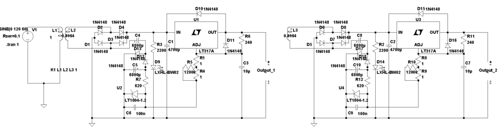
As you can see, the circuit is duplicated twice off of the same transformer, giving me a little less range per output than I originally wanted, but that is the transformer I have to work with (20vct or ~13.2v per output after rectification). The only thing not shown in the model is the output switch. Its a basic psu. Still need to calculate worst case scenario for heat.
All comments and suggestions welcomed! I will now start to work on schematics for the other sections of the bench psu - panel meter supplies and digital output supplies.
Thanks!
So after some input from others, I have decided to stick with LM317 despite its limitations for the main outputs of the psu. I am using a voltage reference to drag the adjust pin down -1.225 instead of a zener for more stability. In spice it seems to work ok. Here is the schematic.
As you can see, the circuit is duplicated twice off of the same transformer, giving me a little less range per output than I originally wanted, but that is the transformer I have to work with (20vct or ~13.2v per output after rectification). The only thing not shown in the model is the output switch. Its a basic psu. Still need to calculate worst case scenario for heat.
All comments and suggestions welcomed! I will now start to work on schematics for the other sections of the bench psu - panel meter supplies and digital output supplies.
Thanks!
You have made the simple 317 look so complicated you have forgotten smoothing capacitance.
Look at the 317 datasheet. Simple circuits !
Look at the 317 datasheet. Simple circuits !
You have made the simple 317 look so complicated you have forgotten smoothing capacitance.
Look at the 317 datasheet. Simple circuits !
Indeed!! My specialty is obfuscation 😛😉
Thank you for the catch. I will revisit the datasheet and see if there is anything else I have forgotten. Sadly, it reminds me that modeling in spice is no substitute for experience - the v. out was smooth as a baby's bottom, in real life the ripple with any appreciable load would have been unusable 😱
Thanks!! 😀
I wanted to know if anyone can suggest a LDO replacement for the LM317? I ask because in post #33 powerbob raises the issue of thermal management when this supply would be used for low voltages.
As a reminder, the xfmrs for the project are two 20VCT 56VA units, I was intending on not using the center tap, getting 28VAC to the separate bridges and the resultant to the v. regulators on individual channels. If the supply is run at low voltages and high amperages, it becomes apparent what the issue is!
Obviously, we can not always have our cake and eat it too, but in case I am overlooking some resources, I would appreciate any input on a replacement for the LM317 that would have a lower dropout and produce less waste heat.
I came across the LT3080 and LT3081, but honestly, I don't understand how they work and despite fewer external components, I couldn't even get it to function in LTSpice 🙁
Thanks in advance! Anyone seen bob?
The WASTE heat is Ipass *(input voltage - output voltage).
Using an LDO reg instead of a 317 does not change the waste heat.
Using an LDO reg instead of a 317 does not change the waste heat.
The WASTE heat is Ipass *(input voltage - output voltage).
Using an LDO reg instead of a 317 does not change the waste heat.
Thank you Andrew! I was forgetting the LDO string of conversation was the low headroom needed to allow for lower valued xfmrs. Apologies....😱
Back to the LM317 and perhaps some strategies to beat the heat!
Would it be better to have multiple Lm317's in parallel to spread the heat? Or as shown in the schematic on page 16 of the datasheet, a darlington pass arrangement?
I still assert that my post #52 has a good assortment of power supply's for the general experimenter.
I think a single variable 0-20v at 1A good enough and you should use your 56va transformers as fixed unregulated power supplies for the reasons given.
If you have a good assortment of fixed supply's the variable supply is not needed vary much. It ends up being used for things like inputs to an op amp or micro A to D, or when you are unsure about something and want to power it up slowly.
Other than the power supply's i listed you might need specialty power supply's you may only use every few years. For example i have a 20v 30A with adjustable voltage and current that sits for years before i need it. The last time it was needed is when a friend wanted to make a "hot wire" to melt wax. We picked out a wire and i dialed up the power supply until the wire melted the wax.
There are a lot of experimenters in this forum, does anyone disagree with my list of good power supply assortment, or have anything else to add.
All power supply's fully isolated from each other, no common ground.
5vdc 2.5 to 3A. If you get into single board computers like the Raspberry pie you will need 2A minimum for there new ver 3.
3.3vdc anything from .5 to 1A.
12vdc .75A to 1.5A , very popular voltage. Do you want to control real world stuff, relays, sensors, motors, etc.
+-15vdc from 200mA to 500mA for op amp circuits.
0-20vdc 1A, just one of these supply's goes a long way. There may be times when you need two of them but it will be once every few years.
You have two 20vac 2.8A transformers 56va. I would use them to there full potential. Make two separate power supply's, simple unregulated. Bridge, bulk capacitor 10,000 to 12,000uF and a .1uF across that. You now have roughly a 24vdc power supply of decent power for experimenting with audio amps. Some audio power stuff can be powered with a single supply and some needs two supply's for +-. Now you can do both.
I did read this initially and honestly couldn't grasp all of it at once. I have reread it several times over the last few days as well as other parts of the thread trying to formulate a plan and a BOM.
Can you elaborate on <<Make two separate power supply's, simple unregulated. Bridge, bulk capacitor 10,000 to 12,000uF and a .1uF across that. >>
Unregulated? No v.regulator, just floating with line level changes?? The capacitance is huge! Wouldn't that cause the fuse to blow? Also, what exactly did you mean with a .1uF cap across that?
Sorry for being slow!
 😱
😱I think it would be great to have a multiposition switch for each xfmr and to incorporate what you mentioned, i.e. position 1 - 0-20vdc 1A supply, p2 - 3.3v 1a, p3 - 5v 2.5A, p4 - 12v 1.5A, p5 - 24v 2.5A. Of course, a second tap selector switch would be required such that I could parallel the windings so that I could have 10vct x2 in parallel to each other and then regulate down from there. I am seeing the selector switch transferring power from the filtered dc output to a regulator board. At first glance, I would need three bridges and three banks for something like this to work. The first bridge and bank could work for the 0-20v, 12v and 24v ranges. The other two bridges and cap banks would be for the 3.3 and 5v circuits where both windings off of the center tap are used to maximize the current. I will try to draw up a functional diagram to clarify my thoughts on this. Thanks for checking in bob!
Make two identical power supply's using your 187E20 20vct 56va transformers.
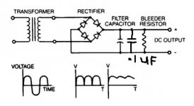
transformer>bridge rectifier>capacitor> bleeder resistor.
capacitor 10,000uF minimum and a .1uf for noise. 10K uF is plenty for most things. But if you use this for an audio amplifier remember that bass notes as in sub-woofer will suck the power out of a power supply. My current audio amp 6 channel class D is powered by an unregulated 24vdc power supply with 100,000 uF. I did not build this supply it came this way.
Bleeder resistor. 20vac x 1.414 = 28.28vdc
28vdc x 10% unloaded = 31vdc
add a little for high line 33vdc.
We want around 1/4 W dissipation.
I = P/E .25w/33vdc = 7.5mA
R=E/I 33vdc/7.5mA = 4.36K
4.7K is very popular size
You might get buy with a 1/2 watt, but get a 1W.
If you have two of these power supply's you can power any high power audio amp chip. Some of the chips just need one 24vdc or higher supply and others need a +- 24vdc or higher supply.
You can also have a SPDT switch on your secondary to switch from center tap 10vac or 20vac to the bridge rectifier. Now you have a 12vdc or so supply good for powering automotive stuff.
You can also parallel the outputs of the two supply's for double the current.
12vdc and 24vdc are very popular for motors and relays (no regulated supply's needed) so you can make high power projects and still be under the voltages that will kill you.
These higher power unregulated supplies tend to take a beating from accidental shorts to overloading. Use the biggest bridge rectifier that you can conveniently mount. Search for bridge rectifier 15 to 25A, 100 to 600vdc.
If inrush is a problem use a. ICL inrush current limiter.
Attachments
Awesome, thanks bob. I will draw up something today and post it. The bleeder resistor is just there to drain off the caps, rendering the system safe after a period of time. Got it! Thanks again for clearing that up for me 🙂
I like to use an indicator that the PSU is alive and working.
Instead of a bleeder I use a series set of Zener + LED (green for good) and a current limiting resistor.
eg. 3mA through the Green LED gives a nice bright indicator, Normal supply voltage is 24V.
Take an 18V Zener and a 1.9V LED. The voltage left to drop through the resistor is 24-18-1.9 = 4.1V Current to be ~ 0.003A therefore the required resistor is 4.1V/0.003A = 1k3 or 1k5
This will bleed down the PSU until 19.9Vdc, then the leakage drops off to virtually nothing.
This can be applied to any PSU and/or amplifier and/or regulator output.
Last edited:
Hi Andrew, agreed, I like that feature as well. I did something similar in post #67 I have an indicator light, D9 fed by R3, just after the bridge, but before the capacitor to the v. regulator. Can you explain why you like to use the zener? Is it to ensure a max amount of voltage that can be seen by the LED thus protecting it from over current? What did you mean by <<this will bleed down the PSU until 19.9vdc, then the leakage drops off to virtually nothing.>>
The Zener prevents the LED shining a GREEN for good, when the voltage has fallen to 18Vdc. A 24V supply should not be sending out only 18Vdc.
You can choose any Zener you want to suit when the indicator will shine "good". And when it turns ON
When the PSU voltage falls to match the LED+ZENER voltage the current that passes through the LED+Zener is virtually zero mA. The LED will not shine. And because the current is virtually zero the bleeder effect is also OFF.
If you believe that there is a risk of dropping a metal tool onto your 19.8V PSU then maybe you should add a bleeder. But I don't
- Status
- Not open for further replies.
- Home
- Amplifiers
- Power Supplies
- Bench Power Supply