Old QSC amps used a small generic shaded pole motor with a fan blade bolted to it. They ran FOREVER. The cheap $4 DC ones were never intended for the same longevity, and TA455’s cost a pretty penny. A surplus AC fan in the smaller form factor used here is still reasonable cost and would last 10 years. They tend to be thicker, and might need to mount on the outside of the chassis, but I’ve done that on my DIY amps before. A temp sensor controlling a relay to shut it down would be a good idea for any remotely-mounted amplifier. Over temp circuits in most amps don’t shut it down until it’s really too late typically. Counting on that to let you know a fan has failed is asking for trouble. It’s meant for “oh, ****, it’s turned up too loud for too long, better not do that again”.
D74 seems odd, it has 600r and 670r, but this is in-circuit... not sure if I should worry about it, seems very early on in the signal path to be a likely issue?
i Have been all over the channel testing components, diodes otherwise all seem good. pulling each resistor seems overkill do you think? i will make a mess if i have too I'm sure!
Ive cut all the outputs off the board now.
With regards to the fan, i will do both amps at the same time, the noise doesnt matter tooo much as its up in the attic and i cant easily change that. So, better flow is more important. Any suggestions for a known fan on amazon or bang good? I am in France...
Rexnord make Indian 4" fans, 1.5" thick, sleeve bearing are $4 here, ball bearing version about $6. 220 VAC.
Utterly good quality, they last years. I have needed to lube the fans after 12 years, and I changed them after 17 years.
One is in a bathroom, and one in spare, still going strong, both are sleeve bearing types.
Replaced as a precaution, some fans had failed when connected in parallel to PLCs, in other places.
Failed short circuit, PLC also failed...
Commonwealth is a Taiwanese brand which is reputed here.
I have no idea of the prices in your location.
Copper has increased in price, so the fans may have gone up slightly in price, and those prices are before 18% tax.
Last edited:
Do something to switch off the amps when not in use, say when you are sleeping.
A thermostat from an oven or electric iron will work as a sensor, you can control a relay with it as it will cut in after a certain temperature. you need to use that to cut the supply.
Or use a temperature controller, thermistor, whatever suits you.
A thermostat from an oven or electric iron will work as a sensor, you can control a relay with it as it will cut in after a certain temperature. you need to use that to cut the supply.
Or use a temperature controller, thermistor, whatever suits you.
Do something to switch off the amps when not in use, say when you are sleeping.
A thermostat from an oven or electric iron will work as a sensor, you can control a relay with it as it will cut in after a certain temperature. you need to use that to cut the supply.
Or use a temperature controller, thermistor, whatever suits you.
The amps are only on when triggered by the 12v trigger from the projector. That 12v switches on a 25a SSR. So not on all the time.
I had intended to do as you say, have a fan on only when the heat sink is hotish. I actually bought some 50c thermal switches. But never got round to fitting them. The original 24v fans were noisy, but as they were in the attic, I just left them. Out of sight, out of mind.
Regards the amp that blew a bridge rectifier, the one that blew was for the 110v rail…the channels from that amp are now in the other one, and one channel is hot and the other stays cold. Just waiting for my son to go to sleep and I will check the thermistor R109 see if is open or not.
ok For a giggle, i put the (hopefully ok now ive resoldered the pcb tracks to the mosfet class H switch as they were badly chard, however the MOSFET checkout ok and so did the diode next to it) channel from amp 1(lets call it the blue amp with the dead outputs and one dead Mosfet, as it has blue pcbs) into amp 2 (with yellow boards with no obvious damage but had a dead bridge rectifier) in place of the channel that was getting hot with no signal, btw the resistance of R109 is 6ohms, thats in circuit. Room temp is about 23c.) and still that channel gets hot with no signal.
Hmm, until i recieve the osciloscope and signal generator i cant really do much else it seems. The BR has arrived, will fit that to yellow today. Hopefuly the outputs will arrive soon for blue channel one today...
Hmm, until i recieve the osciloscope and signal generator i cant really do much else it seems. The BR has arrived, will fit that to yellow today. Hopefuly the outputs will arrive soon for blue channel one today...
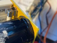
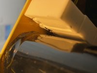
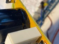

It is usually dried out hot melt..
As a precaution, remove the capacitor, scrape off the glue, and after checking the cap, put it back, or replace it.
The hot melt has been known to become conductive, not nice.
As a precaution, remove the capacitor, scrape off the glue, and after checking the cap, put it back, or replace it.
The hot melt has been known to become conductive, not nice.
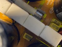
Ok, caps seem ok.
Found a service manual for the identical (mostly) QSC RMX2450. It's handy because, even though not all component numbering is the same, the bias, drivers and outputs are the same. It says 90mv for the bias. And has instructions for the setting of current limiting. My shiny new oscilloscope is here, awaiting a signal generator and replacement MOSFETs!
I've added the manuals here, also, it seems the step fets are known to fail and they recommended them being replaced with Motorola MTP52N06V. See attached service bulitin.
Attachments
Last edited:
Someone mentioned using some kind of alert, for when things are not right ie temperatures in the amp or of the heatsink reach a certain level, to set of some kind of alert, alarm and presumably disable the amp.
Has anyone got any simple ways of achieving this, or maybe a cheap off-the-shelf solution i could install? The amps have to reside in the attic and I have no idea if there's an issue...
Has anyone got any simple ways of achieving this, or maybe a cheap off-the-shelf solution i could install? The amps have to reside in the attic and I have no idea if there's an issue...
A thermostat or heat switch... or a cheap temperature controller, with the sensor near the heat source on the heat sink.
A thermistor is also possible.
Wire the thing in the amp, so it is less easy to bypass.
It should cut the mains input in alarm condition, or at least the power amp section, and let the fans run to cool things down.
Fans you changed?
I would prefer a total shut down for remotely placed equipment.
A thermistor is also possible.
Wire the thing in the amp, so it is less easy to bypass.
It should cut the mains input in alarm condition, or at least the power amp section, and let the fans run to cool things down.
Fans you changed?
I would prefer a total shut down for remotely placed equipment.
Last edited:
Interestingly the schematic may show fans only run when the unit gets hot so normally they may not be running. There also seems to be thermal protection built in but I am not sure exactly how it operates.
Last edited:
I am just saying I am not sure - the power supply is not that easy to understand.
To minimize fan noise, the
fan speed is controlled by varying its actual DC voltage in response
to the amplifier’s heat sink temperatures. An optocoupler isolates
the fan control circuitry from the thermal sensors
To minimize fan noise, the
fan speed is controlled by varying its actual DC voltage in response
to the amplifier’s heat sink temperatures. An optocoupler isolates
the fan control circuitry from the thermal sensors
Last edited:
Just put AC fans powered from the mains switch.
This opto coupler and sensor business is too complex.
So far, unless your attic sees temperatures below -40, nobody ever said their parts died of cold...but they do die of heat.
-40 is and arbitrary figure, it is the same on the Fahrenheit and Centigrade scales.
But most components are okay from 0 Celsius on and up.
Continuous fans will cause less issues than intermittent fans. Or failed fans.
Actually, the variable DC supply is the cause of failure of the fan, at lower voltage it will pull more current, and long term failure life will be shorter.
Idiots.
Should have used a computer type fan designed for variable speed, or used a mains voltage control, like those found in computer SMPS, to run an AC fan...opto coupler and so on are there, they can drive the primary side of a switcher.
And make life difficult for repair people!
Bypass all this, put the biggest fan that will fit, and enjoy the music.
- Home
- Live Sound
- Instruments and Amps
- Behringer EP4000 gone pop x2