Polishing A Turd......
Ok, I have cooked up an impedance measuring jig.
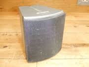
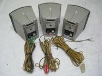
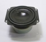
First trial is on little Sony surround speakers....a bit like Bose 'Cube' surround boxes.


Experiment determined 3R3 + 4.7uF NP//1uF PP Zobel network....series switch also connected for A/B comparison purpose.
Subjective result is subtle but nonetheless significant increase in depth information, firming of bass, cleaning and extension of highs, vocals intelligibility much improved.
Previously I couldn't stand these roadkill boxes, now they don't drive me out the room 😱
Without impedance comp they sound slightly but generally 'dirty', with impedance comp they are interesting and listenable, even enjoyable long term.
Ok, these are not full bandwidth speakers, more like AM radio bandwidth, but they are doing the job quite well now.
FR fan boys take note.
Dan.
Haha, bring it on...You're on, Dan ... 😉
Ok, I have cooked up an impedance measuring jig.
First trial is on little Sony surround speakers....a bit like Bose 'Cube' surround boxes.


Experiment determined 3R3 + 4.7uF NP//1uF PP Zobel network....series switch also connected for A/B comparison purpose.
Subjective result is subtle but nonetheless significant increase in depth information, firming of bass, cleaning and extension of highs, vocals intelligibility much improved.
Previously I couldn't stand these roadkill boxes, now they don't drive me out the room 😱
Without impedance comp they sound slightly but generally 'dirty', with impedance comp they are interesting and listenable, even enjoyable long term.
Ok, these are not full bandwidth speakers, more like AM radio bandwidth, but they are doing the job quite well now.
FR fan boys take note.
Dan.
Last edited:
... Experiment determined 3R3 + 4.7uF NP//1uF PP Zobel network....series switch also connected for A/B comparison purpose.
Subjective result is subtle but nonetheless significant increase in depth information, firming of bass, cleaning and extension of highs, vocals intelligibility much improved.
Previously I couldn't stand these roadkill boxes, now they don't drive me out the room 😱
Without impedance comp they sound slightly but generally 'dirty', with impedance comp they are interesting and listenable, even enjoyable long term.
Dan.
Hi ! this indeed sounds very interesting
How did you select the values ? is there a way to simulate anything ?
Thanks and regards,
gino
Hello Gino.Hi ! this indeed sounds very interesting
How did you select the values ? is there a way to simulate anything ?
Thanks and regards,
gino
The values are SOT, ie Select On Test.
If you had a driver measured inductance value you could sort of simulate, however this is a dynamic system being impedance corrected so real measurements are the only properly correct answer....the goal is to achieve a flat impedance/frequency resultant...ie a driver flat impedance characteristic.
There will be some ripples/deviations, however a HF characteristic tending towards flat is the optimal.
You need to sweep the driver to find the minimum impedance value (this will be the R value and the frequency will be somewhere above the resonance hump), and then keep adding capacitance and fine tuning in order to 'null' the rising impedance characteristic.
The method is to measure the voltage across a low value resistor (1R or so, or less) connected between Amplifier Neutral and driver negative.
This resistor effectively transduces the driver current, and you are seeking a constant value of current/frequency....ie a purely resistive load.
Correcting the resonance impedance hump requires an RLC shunt in addition to the RC shunt, and will then allow a very flat overall impedance characteristic, which in my experience is further subjectively very beneficial.
Dan.
Last edited:
this i cannot believe
If it is such a good material why no ones is using it in professional speakers ?
They are. And to further knock a prejudice out of the way, that's the material used in the post-1980 Dynaudio cone drivers, including the one you showed.
To add to the above, this might be a good read written by "our forum's" Lynn Olsen:
http://www.nutshellhifi.com/library/speaker-design2.html
http://www.nutshellhifi.com/library/speaker-design2.html
Hello Gino.
The values are SOT, ie Select On Test.
If you had a driver measured inductance value you could sort of simulate, however this is a dynamic system being impedance corrected so real measurements are the only properly correct answer....the goal is to achieve a flat impedance/frequency resultant...ie a driver flat impedance characteristic.
There will be some ripples/deviations, however a HF characteristic tending towards flat is the optimal.
You need to sweep the driver to find the minimum impedance value (this will be the R value and the frequency will be somewhere above the resonance hump), and then keep adding capacitance and fine tuning in order to 'null' the rising impedance characteristic.
The method is to measure the voltage across a low value resistor (1R or so, or less) connected between Amplifier Neutral and driver negative.
This resistor effectively transduces the driver current, and you are seeking a constant value of current/frequency....ie a purely resistive load.
Correcting the resonance impedance hump requires an RLC shunt in addition to the RC shunt, and will then allow a very flat overall impedance characteristic, which in my experience is further subjectively very beneficial.
Dan.
Thanks for the kind explanation
I think the resulting load should be also less critical for the amp
This is also important because a lot of amp have problem with difficult loads.
Thanks again
Regards,
gino
They are.
And to further knock a prejudice out of the way, that's the material used in the post-1980 Dynaudio cone drivers, including the one you showed
I think that the material used by Dynaudio is a little more complicated than simple PP.
Let's say that there is PP and PP, or not all PP cones are made equal.
By the way i remain on the fact that personally i do not like cone based on plastic, especially thermoplastic polymers.
I listened to big Tannoy monitors with plastic cones (DMT series) and did not like them as much as the other Tannoy with paper cones. Not at all.
And actually are very very less sought after in the market. Very very less ...
Great box by the way.
An externally hosted image should be here but it was not working when we last tested it.
The woofer in the Behringer should cost some 20-30 USD at maximum.
It is not possible to get a quality driver at that price.
It is clearly not a strong point of the speaker, and the woofer is very important.
Cheap and good tweeters are more common.
Thanks and regards,
gino
Last edited:
Hi, have you had much of a chance to to experiment yet at all?
This site has quite a bit of info about the B2031P, and it seems that stuffing the ports improves the response as reduces diffraction:
audio blog: More on the B2031P and diffraction
The measurements speak for themselves, and even though it isn't the same model, the enclosure design looks very similar to the B2031A. I think this would be the first thing I would try before taking them apart. 🙂
Not sure if your question was directed at me....anyway as I write, I am building a jig (a bridge network sending a differential signal to my N&D set) in order to rapidly and easily measure/compensate drivers, and boxes.Hi, have you had much of a chance to to experiment yet at all?
This bridge will allow me to establish the R value accurately at different power levels, and then it should be a simple matter to sweep the driver/box and adjust the C value.
Except for recently, I have not used my Behringers in anger for a very long time (they have been in storage).
When I did use them daily, I do recall that stuffing the ports did improve their overall sound, and quite markedly.
One problem with these cabinets, is that the plastic front moulding excites and rings quite strongly audibly.
I did apply some mass/damping material to the back of this plastic moulding and this did improve matters markedly.
This was a work in progress at the time, so nothing properly conclusive yet, but in the near future I should have some definitive results, now that I am back on their (the Behringers) case.
I have kept one cab in factory condition as a reference.
My approach in this instance is to get the drivers electrically correct before embarking on any electronics mods.
It ought to be interesting to see/hear the differences this kind of tweaking can make to an otherwise, actually quite good pair of speakers.
Dan.
Haha, bring it on...
Ok,
I have cooked up an impedance measuring jig.
Hi,
That you can pointlessly zobel drivers and measure
the obvious impedance change is irrelevant as fact.
The facts are zobelling a driver has no real effect
with decent low output impedance amplifiers
unless some significant impedance is placed
in series with the driver or the amplifier has
significant source impedance, most don't.
Yuor musings on zobelling a cheap speaker are a
fine example of someone deluding themselves
that they can hear significant differences that
simply do not exist, and cannot be measured.
rgds, sreten.
I have not Zobeled these speakers yet, and I have not made made any claims as to the audibility of the changes that will be implemented, yet.
Considering that the amplifiers/power supplies/layout in these monitors are less than optimal, I think that you are best to ignore this thread, or just plain butt out.
Here's a link, just for you...Zobel Networks
Dan.
Considering that the amplifiers/power supplies/layout in these monitors are less than optimal, I think that you are best to ignore this thread, or just plain butt out.
Here's a link, just for you...Zobel Networks
Dan.
Last edited:
I have not Zobeled these speakers yet, and I have not made made any claims as to the audibility of the changes that will be implemented, yet.
Considering that the amplifiers/power supplies/layout in these monitors are less than optimal, I think that you are best to ignore this thread, or just plain butt out.
Here's a link, just for you...Zobel Networks
Dan.
Hi,
Its those operating on false premises and
subjective opinions who should "butt out".
Making the drivers "electrically correct" is false premise,
as there is no reason driver zobels would improve any
compentently designed amplifier. In active speakers
the amplifiers will have any zobels required fitted.
Adding driver zobels will just waste current and power.
Pure conjecture is not sound useful technical advice.
rgds, sreten.
Hi,Pure conjecture is not sound useful technical advice.
rgds, sreten.
I already stated that those little Sony boxes sounded different with Zobel network switched in or out.
So what is your problem...is it reading or is it comprehension.
So you are an electrical engineer....you ought to understand load matching.
In this case of audio amplification we are dealing with a NFB system, and reactive load implies reflected energy....think about it.
Dan.
Standard Theory, And Standard Practice...
Dan.
Yeah right, sure thing 🙄.Hi, In active speakers
the amplifiers will have any zobels required fitted.
Dan.
Those that claim to hear differences need to show measured proof or its all just subjective conjecture, Advising people to just use your ears to design a speaker is foolish. This isn't the 1950's. There are free to very inexpensive ways to design a speaker system using MEASUREMENTS and people need to learn how to use them instead of throwing parts at a speaker and calling it a day.
I think that the material used by Dynaudio is a little more complicated than simple PP.
It's mineral filled. That's also true of 99% of PP cones. They're not doing anything special. Their material is quite thermoplastic, so get rid of that prejudice as well.
What are the typical minerals, and in what form ?.It's mineral filled.
Dan.
Lots of them. Calcium carbonate and silica are the most common (carbon black is added for appearance, ditto titanium dioxide). They're usually added as a masterbatch concentrate at the molding machine hopper, but there are certainly compounders who will happily do the work for the molder and deliver homogeneous filled resins.
The exercise is not to "design a speaker", active in this case. That's already been done - from my POV, it's to see where are obvious, and some less obvious, weaknesses in the execution, and to eliminate them one by one.Those that claim to hear differences need to show measured proof or its all just subjective conjecture, Advising people to just use your ears to design a speaker is foolish. This isn't the 1950's. There are free to very inexpensive ways to design a speaker system using MEASUREMENTS and people need to learn how to use them instead of throwing parts at a speaker and calling it a day.
Like most standard setups the sound starts to fall apart, depending upon the material, once a certain volume is reached - as an example, it's not very capable on solo piano, if you try and go for a decent acoustic level. This is nothing to do with driver refinement, other gear I have here with speakers nowhere as good as those in the Behringer easily humiliate the latter at higher volumes - because they're being driven by a clean electrical signal.
Last edited:
The exercise is not to "design a speaker", active in this case. That's already been done - from my POV, it's to see where are obvious, and some less obvious, weaknesses in the execution, and to eliminate them one by one.
Like most standard setups the sound starts to fall apart, depending upon the material, once a certain volume is reached - as an example, it's not very capable on solo piano, if you try and go for a decent acoustic level. This is nothing to do with driver refinement, other gear I have here with speakers nowhere as good as those in the Behringer easily humiliate the latter at higher volumes - because they're being driven by a clean electrical signal.
Finding the obvious weaknesses are easy when you have the knowledge to do so based upon the frequency, phase, distortions and impedance of the speaker. Deciding to remove, replace or change components by ear only is throwing away good money and time. Why spend months trying to get a desired result when you could have done it in weeks or even days?
Sorry I don't buy into your theory that you can't have a speaker that sounds great on any type of music. The days of east coast sound vs west coast sound has been over with for decades now. It's quite easy to have a speaker that can reproduce a piano's sound and also play loud. That is if you designed the speaker to have the right components and integrated them with a proper box and crossover be that either passive or active. I don't see any proof that your lesser speakers "humiliate" the Behringer yet. A clean signal is important in any audio system, we aren't talking about driving an amp to clipping, who would do that?
- Status
- Not open for further replies.
- Home
- Loudspeakers
- Multi-Way
- Behringer B2030A modification project.