hi,
Can you please send me the Schematic of the A500.
please send it to coolwater4748(at)hotmail.com
Thank you very much.
kind regards
Can you please send me the Schematic of the A500.
please send it to coolwater4748(at)hotmail.com
Thank you very much.
kind regards
I'd be very interested in the Behringer A500 schematics, if any of you fine gentlemen can be bothered to send it over to the below listed email address it would be very much appreciated!
ssassen-at-hardwareanalysis-dot-com
Cheers,
Sander.
ssassen-at-hardwareanalysis-dot-com
Cheers,
Sander.
On Youtube there is a video that shows increased distortion using the A500 volume control at 60-70%
YouTube - ebaystars's Channel
I thought this might be of interest to A500 users out there!😀
YouTube - ebaystars's Channel
I thought this might be of interest to A500 users out there!😀
this is NOT volume control, it is Gain control.
Stupid design, only sick mind can do things like this. Changing input resistor of inverting opamp to control gain...this is crazy. Whole input section should be redesigned
Stupid design, only sick mind can do things like this. Changing input resistor of inverting opamp to control gain...this is crazy. Whole input section should be redesigned
Hi Stormsonic,
What do you mean by "gain control"?
You don't control the gain in any active circuitry. Feedback goes to OP-amp non inverting input.
Or have I misunderstood your post entirely?
What do you mean by "gain control"?
You don't control the gain in any active circuitry. Feedback goes to OP-amp non inverting input.
Or have I misunderstood your post entirely?
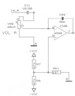
yes, this is crazy design. With potentiometer you change the gain of inverting opamp, not attenuating input signal. Resistors R66 and R67 are not there on real PCB (empty pads). They exist only on shematic
Hi,
According to the schematic you don't alter op-amp gain by turning the pot, its just an attenuation.
The feedback loop enters the op-amp non inverting input. This is because the speaker output is already inverted relative op-amp output. Inverting twice would result in positive feedback not negative.
Think very different with this amp.
The - input of the opamp is not the summing node,
it is not inverting in the sense that you mean. Amplifier gain
is set by R10/R61 at about 32dB.
It would probably be a good idea to have a resistor for R67, if the pot goes open during rotation
the opamp would loose input bias and latch to the rail.
I would suggest about 100K for R67. C11 should have a film bypass too.
I would like to see 'some' resistance on the input to pin 6. If the pot wasn't there that would be R66.
With the pot wide open and a bad ground loop, it would likely ruin IC2B (I've had it happen).
Unless there is more circuitry than what is shown here, the 'clip' LED is more of a distortion alert.
On musical transients the LED will not be visibly bright until it has been on about 40mS or so (40mS
is about what the pesistance of vision is). Audibility of distortion may be on the order of %10 if of less
than 1mS duration, at 40mS the threshold is about 0.3%, so this circuit is more of a distortion
alert than a clip circuit (although on steady-state signals it will be accurate).
stormsonic,
The schematic you wanted to show is not visible.
Do you agree now in that the volume pot does not alter Op-amp gain?
The schematic you wanted to show is not visible.
Do you agree now in that the volume pot does not alter Op-amp gain?
Last edited:
On Youtube there is a video that shows increased distortion using the A500 volume control at 60-70%
YouTube - ebaystars's Channel
I thought this might be of interest to A500 users out there!😀
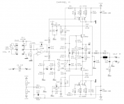
Not surprising considering the connection of C53. Note that this capacitor does not exist in the QSC schematic and thus it should not have the distortion problem:
http://www.qsc.com/support/library/schems/Discontinued/Series One/1200.pdf
The QSC uses another opamp and a different value of the capacitor in parallell with the feedback resistor however.
Hello
Someone please send me the Schematic of the A500?
I have one with a channel that it has a "random" protection insertion.
Sometime after 20 seconds, or 2 hours....
please send it to maunoni@yahoo.it
Thank you very much.
best regards
Someone please send me the Schematic of the A500?
I have one with a channel that it has a "random" protection insertion.
Sometime after 20 seconds, or 2 hours....
please send it to maunoni@yahoo.it
Thank you very much.
best regards
- Home
- Live Sound
- Instruments and Amps
- Behringer A500 as a DIY project