adding resistor in series gives you greater span of useful rotation of trimpot
think how voltage potential is distributed along resistor attenuator cell
it'll be ideal to divide that resistance , from output node ( being at approx. U/2) to approx. 4V ( needed at mosfet gate) to 3/4 and 1/4 ....... meaning - say 15K fixed and say 5K trimpot
that way you'll have voltage available at trimpot in range of 0 to some 5V ...... but for practical purposes , without splitin' da hair , 10K +10K is ok
adding resistor in series gives you greater span of useful rotation of trimpot
think how voltage potential is distributed along resistor attenuator cell
it'll be ideal to divide that resistance , from output node ( being at approx. U/2) to approx. 4V ( needed at mosfet gate) to 3/4 and 1/4 ....... meaning - say 15K fixed and say 5K trimpot
that way you'll have voltage available at trimpot in range of 0 to some 5V ...... but for practical purposes , without splitin' da hair , 10K +10K is ok
ok, copy, and a big thanks...
I have two ACAs that I am running as bridged monoblocks (v1.6 with 24v supplies). They sound great, however, I prefer the sound of the amp in the true single-ended stereo configuration. It is just short on power into my 12 ohm speakers (they are listed at 97db, but I don't know if they truly are that efficient).
A stereo ACA is not the same as a bridgedACA = bACA, not only that you are running balanced, in that the already highish output impedance ACA is doubled when bridged.
This takes you from the same speaker matching issues of a low (for an SET) output impedance somewhere into the higher range (for a SET). 12Ω speakers help (and i factored that in), but the speaker impedance could well affect the sound you are getting. And, althou you might get some leow level detail smearing because of the 2 devices in parallel, it will retain the same SE signature.
What happens when you parallel the ACAs into monoBloks (pACA)? That halves the output impedance (less of a change magnitude wise than going the other way).
What speakers? What does the impedance look like?
dave
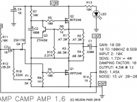
the ACA was even mistaken for a 300b amp...
In some senses they are similar. Similar power, similar output impedance (so same speaker atching issues) both SE, but you can build an ACA for less than the cost of the 300Bs.
dave
Funny fact "baca" in polish means highlander, Who has sheeps....
to us, that means a cow, to the japanese, that is a swear word....😀
In some senses they are similar. Similar power, similar output impedance (so same speaker atching issues) both SE, but you can build an ACA for less than the cost of the 300Bs.
dave
bang for the buck....
Indeed. From the numbers i have received so far that the ACA has exceeded 3k channels. That likely makes it the most popular hiOutput impedance amplifier in the population.
dave
dave
Thanx.
3 is what Nelson specced as damping in V1.
A damping factor of 10 yields Rout of 10/8 = 1.25 or 2.5Ω for bACA, and 0.65 for pACA.
That is very useful information.
Now, i expect that the actual output impedance varies with frequency it would be nice to have an actual measurement of Rout instead of a single number damping factor.
Thanx Tony.
dave
i doubt that it will vary much with frequency, NP amps do not use zobel networks/boucherot cells, which lowered damping at mids to high frequencies...
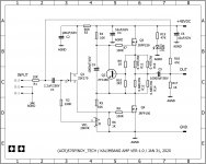
big ACA, scheme ready, layout ready....
thinking of the sk117, instead of sk170...
and a 0.2ufd at the bottom of the 330k resistor to trimpot...
may improve transient response some?
thinking of the sk117, instead of sk170...
and a 0.2ufd at the bottom of the 330k resistor to trimpot...
may improve transient response some?
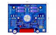
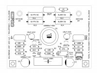
Attachments
Last edited:
@TonyTecson, you didn't do anything to increase the standing current.
not there yet, that will depend on the actual heatsink that i can lay my hands on, a conrad engineering 350mm x 150 mm x 60 mm is what i am intending to use...we will see...not closing my doors to higher bias..
increasing standing bias can be done by changing the two 0.68 ohm resistors to say two 0.47 ohms, but i do not want to do this just as yet..
Last edited:
That’s a good looking PCB layout. This will be a fun project and a nice amp to listen to.
I would suggest changing the two 0.68 Ohm resistors to 0.56 Ohms. That should raise the bias current to about 1.6 Amps. The IRFP150s will sound better with higher bias.
R4 should probably be increased to 15k.
I would suggest changing the two 0.68 Ohm resistors to 0.56 Ohms. That should raise the bias current to about 1.6 Amps. The IRFP150s will sound better with higher bias.
R4 should probably be increased to 15k.
Last edited:
big ACA, scheme ready, layout ready....
thinking of the sk117, instead of sk170...
and a 0.2ufd at the bottom of the 330k resistor to trimpot...
may improve transient response some?
while you are there , increase R5 to 15K , decrease VR1 to 5K (max 10K)
🙂
- Home
- Amplifiers
- Pass Labs
- Beefed up Amp Camp Amp?