A bad silver joint on the AVCC or its board-to-board connectors could cause both of these problems. It is where I would look first.
I would concentrate on the male and female headers. Check pin continuity first, without pressure if possible (check from connected pads rather than the pins themselves).
Hi Brian,
thanks for your fast replies and very good help!
I re-soldered the headers and some components with not so good looking solder joints. Now the hiss is goon (hurray!), but the hickups are still there. (Perhaps they are now not so often.)
So, do you have an idea?
What are the recommended jumper settings for the B3?
Some other thoughts:
A few times per hour the MPD on BBB isn't responding for some while. I expect this to be because he's loosing connection to the B3 (then Lock-LED is off), but I'm not sure.
Do you or anybody have/has some ideas how to proceed or what so check?
The hiss is back! 😕 
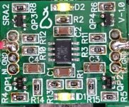
Hm, could there also be an connection problem within the board-to-board connectors of the AVCC? If I touch the small 3-legger of the AVCC (OP-3, opamp #3), the hiss goes away. By the way, the opamps are fairly hot.
Could there be an oscillation in the AVCC causing one of the mentioned problems? (LOCK problem, hiss)
The hiss is back! 😕
Hm, could there also be an connection problem within the board-to-board connectors of the AVCC? If I touch the small 3-legger of the AVCC (OP-3, opamp #3), the hiss goes away. By the way, the opamps are fairly hot.
Could there be an oscillation in the AVCC causing one of the mentioned problems? (LOCK problem, hiss)
I think you are referring to QP3 (transistor). You could try touching the three legs of the transistor with your soldering iron to make sure they are bonded well. It is possible that the joint was damaged when soldering/resoldering the headers.
Can you post a picture of your AVCC, top and bottom?
Hi Brian,
thanks for your reply!
I'll do the rouching and will report back.
Also I'll take a photo and post it, but unfortunately the back of the pcb isn't easy to reach because of the cables you can see in picture 1 and post
I got a new oscilloscope, if this helps, but I didn't have a lot time to dive into using it. Basically measures will be fine, but I'm a bit afraid of some part-knowledge of the past: "Be carefully with the grounding when using an oscilloscope."
I assume you did not use the male/female connectors for mounting the AVCC module. Too bad, as it makes life a lot easier for troubleshooting.
Yes, I did, but as I switched from Legato III to another IV stage, I needed to solder a wire from AVCC's 3.3V pin. This is why I first had to remove the soldered wire, the rest is just lifting the pcb.
What's on the lower side of the pcb?
What's on the lower side of the pcb?
Soldered all joints in the AVCC, the hiss is still there.
Directly after turning in the DAC it had very regulary connection losses (and it takes several seconds up to perhaps a minute to reach a lock again), but after let's say 30 minutes it improves a lot. (Hick-ups ever few minutes, so sometimes you can listen to one or two songs without disturbance).
So, there seems to be a problem with a temperature dependent device.
Any educated guesses what comes next?
PS:
The pictures will come tomorrow.
More pictures...
PS:
I solved the hickup, so the lock-problem seems to be solved. The hiss remained.
PS:
I solved the hickup, so the lock-problem seems to be solved. The hiss remained.
Attachments
Last edited:
You press the board more firmly toward the Buffalo and the hiss vanishes? Pressing with a bare finger or pressing with something insulated/non-conductive?
Hi Francolargo,
many thanks for reading my stuff and for your thinking!
After the soldering the hiss noise went a bit down but stays now at the same level. But I don't know how this is reasonable connected:
1 Had there been a bad solder?
2 Did the mechanical movement of the soldering changed some connection somewhere?
If I put my bare finger softly on one of the transistors, then the hiss goes away. I will repeat this this evening with a non-conductive thing to check if it is because of some electrical connection, mechanical influence or the fact that my finger also cools down the little 3-leggers.
I'll report back.
PS:
I'm not experienced with measurement with a oscilloscope, but now I own one. Don't want to destroy something something, because I hadn't have time to dive into it, so do you have an idea if this could be put to any use here and how?
If bare finger helps but non-conductive pressure does not, then the remote possibility of radio frequencies in the power line might be worth considering.
Think of an oscilloscope as a voltmeter in the y axis with time in the x axis. You could check for noise in the supply to and output from the regulator. Just don't fry the ES9018 - not nice when that happens. [Now, my personal non-engineer approach would be to make sure the supplies to the AVCC are clean, and if so, then just put in a new AVCC! But that is just me! Life is short! 😉 ]
Good luck!
I Bought and re-assemble the BBB / Hermes /Cronus /Rhea set to use in combination with the DDDAC.
Configuration: BBB element14 / Hermes / Cronus / Rhea (X1= 22.5792M
/X2 =24.576M), divider on 1:1
The DAC is connected to Cronus: Ground -> Ground, BCK-> DCK,
LRC -> D1, Data -> D2
All the 4 leds on the Hermes shining bright.
Unfortunately after installing Botic4 and 5 using Play <Filename>, I get also the "play FAIL sox: `default' Device or resource busy: Operation not permitted” error
I used: 44.1 and 48 khz files Flac’s and Wav’s, It doesn’t matter.
Measure connection all the headers
Re-tip al connections: no effect
BBB switch on before DAC or afterwards the DAC : no Effect
Divider on 1:2: no effect
Clock1 remove, the other remove: no effect
(Tried) Settings of the Botic driver:
Ser.congfig: MMMM, IIII, -I-- and I---
Dai.format: 16385, 4097
DSD.format.Switch: Off and On
What works: The DDDAC worked well with the Raspberry Pi with the I5 header.
BBB with USB works.
Voltage on D1 of Cronus = 3.3V
Another (big) problem is my lack of electronical knowledge and I have no oscilloscope. I’m just depended on the help of the experts on this side. Maybe this project is just to complicated for me.
This problem seems to appear to several user. Is there maybe a common problem and/or a general way to solve this ? Often it’s seems to be a hardware problem.
Which Botic parameters should I use for a PCM-DAC without Clock, and the 22M/25M Rhea’s ?
Sorry for the long mail and many questions but I’m stuck.
Thank you in advance and greetings,
Sjoerd
Based simply on reading (my own BBB/Hermes/Cronus has always worked well) I would look first for a problem with Cronus and its supply of the correct clock to the BBB. I get the error you mention when I forget to turn on power to Cronus.
Perhaps a fresh install of Botic v5 wouldn't hurt. To configure clocks see http://bbb.ieero.com
--------------------
Clocks configuration
--------------------
Installed clocks are configurable via:
- kernel option snd_soc_botic.ext_masterclk
Examples:
0 ... no external clocks, just onboard for 48k freq
1 ... external clock for 44k1 + onboard for 48k
2 ... external clock for 48k only
3 ... external clocks for 44k1 and 48k (default)
+4 ... invert polarity of clock selection switch GPIO0_15
9 ... external clock for 44k1 only
Good luck!
Sjoerds' problem
Hi,🙂
don't know if this will help, but, give this a look, your problem looks like the one I had.......
http://www.diyaudio.com/forums/twisted-pear/274476-bbb-botic-cape-play-problem.html#post4327448
I Bought and re-assemble the BBB / Hermes /Cronus /Rhea set to use in combination with the DDDAC.
Configuration: BBB element14 / Hermes / Cronus / Rhea (X1= 22.5792M
/X2 =24.576M), divider on 1:1
The DAC is connected to Cronus: Ground -> Ground, BCK-> DCK,
LRC -> D1, Data -> D2
All the 4 leds on the Hermes shining bright.
Unfortunately after installing Botic4 and 5 using Play <Filename>, I get also the "play FAIL sox: `default' Device or resource busy: Operation not permitted” error
Sjoerd
Hi,🙂
don't know if this will help, but, give this a look, your problem looks like the one I had.......
http://www.diyaudio.com/forums/twisted-pear/274476-bbb-botic-cape-play-problem.html#post4327448
Based simply on reading (my own BBB/Hermes/Cronus has always worked well) I would look first for a problem with Cronus and its supply of the correct clock to the BBB. I get the error you mention when I forget to turn on power to Cronus.
Perhaps a fresh install of Botic v5 wouldn't hurt. To configure clocks see http://bbb.ieero.com
Good luck!
Hi Franco,
Thanks for your reply, I set the clocks on 3. Because I'm not playing DSD, I set the serializer on I--- and DSD-switch off. Dai-Format default. I'm playing a little bit with the settings, but I like to known if some settings matters, just to save time and discard options. I compensate my lack of knowledge with a lot of patience. 🙂 . Hopefully I'm founding the answers by excluding the things that's going well. I installed Botic V4 and V5 (using your 3 commands) many times :-( . Different Debian versions. There is power on the Cronus. On my work, I could tested the clocks and they are OK. (Someone at home let them fall, I want to exclude a defect clock). I think about two causes: Some bad (solder)connection or the DDDAC and the Cronus doesn't match? somewhere. So next I plan (try) to re-assemble/resolder the boards
regards,
Sjoerd
Hi,🙂
don't know if this will help, but, give this a look, your problem looks like the one I had.......
http://www.diyaudio.com/forums/twisted-pear/274476-bbb-botic-cape-play-problem.html#post4327448
Hi Ichiban,
Also thanks for your reaction. Yes, I know this link. I founded this thread by Google-ing the error message 🙂 . I tried to tip all the solder-connection, including the clocks, but it doesn't work yet. Next I gonna re-assamble/resolder all the boards, maybe that helps.
Regards,
Sjoerd
Hi ACvB,
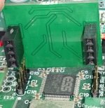
please measure carefully DC voltages during the playback (before it fails with error) on pins from the picture.
The value of the voltage is important only for 3.3V pin. Others can be arbitrary non-zero, e.g. between 0.5V - 3V.

The MCLK and 3.3V signal is generated by Cronus. They should be non-zero if the Cronus and Hermes-BBB is powered on.
The BCLK and LRCK are generated by BBB/Hermes-BBB and they are active only during the playback... e.g. while "play" command is running.
Use the GND of Cronus power connector as ground reference for Voltmeter.
please measure carefully DC voltages during the playback (before it fails with error) on pins from the picture.
The value of the voltage is important only for 3.3V pin. Others can be arbitrary non-zero, e.g. between 0.5V - 3V.
The MCLK and 3.3V signal is generated by Cronus. They should be non-zero if the Cronus and Hermes-BBB is powered on.
The BCLK and LRCK are generated by BBB/Hermes-BBB and they are active only during the playback... e.g. while "play" command is running.
Use the GND of Cronus power connector as ground reference for Voltmeter.
Last edited:
- Status
- Not open for further replies.
- Home
- More Vendors...
- Twisted Pear
- BBB/Botic/Cape play problem