But does it still function well as a Class-D-clipping-avoider (for lack of a better term)??I had to lower the 470k to 220k, otherwise there isn't enough voltage across the 22k resistors to turn on Q1 & Q2 at all, even with input level turned up until the op-amp output stage starts to clip at around +/- 13 V (with +/- 15 volt supply rails.) A quick voltage-divider calculation confirmed this. Once R42 was lowered to 220k, the circuit does clip symmetrically, but in the simulator it seems to have the usual fairly abrupt-onset clipping typical of solid-state diode clipping circuits, i.e. it is not soft and progressive, but goes from completely clean at 0.2 V input to significantly clipped at 0.25 V input (which is less than +1 dB increase in signal level.) I built dozens of diode and transistor distortion circuits similar to these in my twenties, and personally, I was disappointed with the results every time.
-Gnobuddy
With the discussion on Nigel's circuit, and JM Fahey's, I was thinking more along the lines of "If I don't have a Joyo American Sound, is there something I could DIY to make a guitar sound less thin, cold, and sterile than just a clean SS amp?"But does it still function well as a Class-D-clipping-avoider (for lack of a better term)??
For just limiting the signal, I wouldn't bother with anything very complex. I'm betting a simple pair of anti-parallel diodes followed by a trimpot will do that job well enough. Just pick diodes or LEDs that clip at slightly higher signal voltage than the power amp requires to reach full power, then set the trimpot so the diodes clip and the amp just doesn't.
Most of the class-D boards I've looked at have jumpers or switches that let you set various amounts of voltage gain. Between that and the wide variety of LEDs and diodes available today, I think it shouldn't be too hard to make this work. The exact thing I don't like about diode-clipping guitar distortion pedals (the abrupt onset of distortion) makes them well suited for this job (i.e. limit the signal so the amp never overdrives, but don't add a lot of distortion when the signal is smaller.)
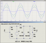
For giggles I threw a passive resistor-diode limiter like this into LTSpice; V1 is the incoming signal, R1 keeps the diodes from shorting out the incomng signal, D1 & D2 limit the signal, and R2/R3 is a 100k trimpot. There are only four components to the clipper: R1, two diodes, one 100k trimpot.
Vo is the output signal from the diode clipper, going on to the class-D power amp board.
Resistors R4/R5 are not part of the limiter, they are only there in this demonstration circuit to divide down the incoming signal so that it is exactly the same as the outgoing signal at low amplitudes (when the diodes do nothing.) This lets us compare input and output signals to see what, if anything, the limiter is actually doing.
The blue waveforms are the input signal, the green ones are the output signal.
When V1 is 50 mV peak, the output is identical to the input (traces overlap perfectly, you can't see the green.)
When V1 is 300 mV peak, the diodes just start to limit the outgoing signal - the green trace is almost identical to the blue trace, but just a hair smaller at the peaks.
When V1 is 550 mV peak, the diodes are clamping the signal peaks to about +/- 320 mV, even though the incoming signal goes up to +/- 400 mV.
Further increases in V1 beyond this produce very little increase in the output signal.
If the signal amplitude is too small when 1N4148s are used, one could use two diodes in series in each direction, or use LEDs instead of silicon diodes to raise the signal level at which clipping starts. For example, I measured voltage drop across one of my red LEDs at about 1.7 volts just the other day.
-Gnobuddy
Attachments
OK. Let's say I want 14 db peak-to-rms headroom; I don't think that is unreasonable. So that means at the start of clipping (300mv peak), I can have only 12 mv of rms signal. Hmmmm......that's pretty low. Maybe a Zener in series with each 1N4148?For just limiting the signal, I wouldn't bother with anything very complex. I'm betting a simple pair of anti-parallel diodes followed by a trimpot will do that job well enough. Just pick diodes or LEDs that clip at slightly higher signal voltage than the power amp requires to reach full power, then set the trimpot so the diodes clip and the amp just doesn't. Most of the class-D boards I've looked at have jumpers or switches that let you set various amounts of voltage gain. Between that and the wide variety of LEDs and diodes available today, I think it shouldn't be too hard to make this work. The exact thing I don't like about diode-clipping guitar distortion pedals (the abrupt onset of distortion) makes them well suited for this job (i.e. limit the signal so the amp never overdrives, but don't add a lot of distortion when the signal is smaller.) For giggles I threw a passive resistor-diode limiter like this into LTSpice; V1 is the incoming signal, R1 keeps the diodes from shorting out the incoming signal, D1 & D2 limit the signal, and R2/R3 is a 100k trimpot.
When V1 is 300 mV peak, the diodes just start to limit the outgoing signal - the green trace is almost identical to the blue trace, but just a hair smaller at the peaks.
When V1 is 550 mV peak, the diodes are clamping the signal peaks to about +/- 320 mV, even though the incoming signal goes up to +/- 400 mV.
Further increases in V1 beyond this produce very little increase in the output signal. If the signal amplitude is too small when 1N4148s are used, one could use two diodes in series in each direction, or use LEDs instead of silicon diodes to raise the signal level at which clipping starts. For example, I measured voltage drop across one of my red LEDs at about 1.7 volts just the other day. -Gnobuddy
Last edited:
I think this is an entirely different calculation, determined by how much maximum power your amp can put out, and how much average power you intend to use. For example, if your amp has 15 watts maximum output, and you want to stay 14 dB below that, then you have to use an average power of no more than 597 mW. (i.e., 14 dB less than 15 watts is about 600 mW.)Let's say I want 14 db peak-to-rms headroom
If you're playing at an average power of 600 mW, you can now get up to 14 dB louder before your amp begins to clip (at 15 watts.) If I understood you correctly, this is the headroom you're talking about.
Incidentally, 600 mW is about 2.2 dB less than the 1 watt reference level at which speaker sensitivity is usually measured. If you have a speaker rated at 100 dB@1W @1 metre, and you drive it with 600 mW, it will still be very, very loud: nearly 98 dB@ 1 metre. To put that in perspective, several online loudness tables suggest that a typical household vacuum cleaner puts out about 70 dB SPL. 98 dB is 631 times more than 70 dB. So with 600 mW into a 100 dB@1W guitar speaker, you create about the same loudness as 600+ vacuum cleaners at 1 metre distance. 😱
To work out at what voltage the limiter should kick in, we can estimate the maximum output voltage of the power amp, then divide it by the power amp's voltage gain to find the maximum input voltage the power amp needs....at the start of clipping (300mv peak), I can have only 12 mv of rms signal.
I'm using a nominally 20 volt battery. The chip runs in bridge mode, where maximum peak output voltage equals the battery voltage, less about 3 volts for losses. Call it about 17 volts peak, maximum sine wave output voltage to the speaker.
The class-D board I'm using has a pair of microswitches on it that can set the gain to 25.6 dB, 31.6 dB, 35.1 dB, or 37.6 dB.
Let's pick the highest gain as an example; 37.6 dB of voltage gain is the same as a voltage ratio of 75.86 times. Since the maximum voltage out of the amp is 17 volts, the amp needs (17 volts / 75.86) input signal volts to just reach maximum output. That calculates to 224 mV, peak.
So the signal from the trimpot across the limiting diodes should be adjustable up to about 225 mV, to make sure the class-D amp is able to reach (nearly) full power, without actually running into hard clipping. In practice I think I would probably set it to keep the amps output maybe 1 dB less than maximum, which translates to about 12% less voltage, or around 200 mV peak.
LTSpice thinks the simple clipper with two anti-parallel 1N4148 diodes will limit at around 320 mV peak, which means we can use the trimpot immediately following to dial this down to 200 mV. In other words, if my class D board is set to 37.6 dB gain, I power it from a 20 V battery, and make a limiter with a pair of 1N4148 diodes, LTSpice thinks it will all work well together once the trimpot is properly set.
We shouldn't trust a simulation 100% (it's only as good as the mathematical model of the diodes), so this will have to be verified in real life, on the test-bench, with a 'scope and signal generator and dummy load instead of the speaker(s).
Incidentally, if I set my class-D board to its minimum voltage gain (25.6 dB) and repeat the calculation, it will need nearly 900 mV input (peak value) to just reach full power. In this case, a pair of 1N4148s in anti-parallel won't put out enough voltage, so I'd probably try a pair of red or green LEDs instead.
Probably the simplest thing to do is just use the LEDs, that way the trimpot can be used to set proper clipping for any of the four selectable gains of the class-D board.
-Gnobuddy
What am I missing? Looking at the graph, it seems that the limiting begins at ~ 220 mV, not 300mV. Do the diodes really gently compress as the graph indicates?
I think maybe you and I have very different expectations from this circuit. This is a very simple little circuit that I think will be adequate to keep away the sound of hard class-D clipping when used with guitar. It is by no means a proper Hi-Fi limiter of the sort used on expensive professional P.A. systems - those contain lots of components (op-amps, gain cell, precision rectifier, RC networks for attack & release time constants, etc.)What am I missing? Looking at the graph, it seems that the limiting begins at ~ 220 mV, not 300mV.
For this simple four-component clipper/limiter, the distortion at 220 mV out is less than 1% (using the FFT in LTSpice.) Nobody can hear 1% THD added to an electric guitar (guitar pickups already generate lots of distortion). Even your eyes wouldn't spot the tiny distortion at 220 mV if the undistorted sine wasn't there to compare it with.
With the component values in the simulation, the 220 mV output level occurs when V1 is 300 mV peak.
If you now increase V1 all the way to 550 mV peak, the output peaks are rounded off at about 320 mV. Distortion is now up to maybe 10% THD. That would be far too much for Hi-Fi - but for guitar?
Fender Blackface "clean" is already several percent THD, maybe even 10%. We would hear 10% THD from this diode clipper, sure, but I think it would be like a Tube Screamer set for very slight distortion - a guitar sound that nobody would raise an eyebrow at.
Put another way, 225 mV is about 3 dB less than 320 mV. So the output of this limiter will produce negligble distortion (< 1%) when V1 is 300 mV, then jump to 10% THD if you increase V1 to 550 mV. The input signal increased by nearly 6 dB, the output by only 3 dB. That's pretty gentle compression, though it will get more extreme if the input is turned up even more.
Remember, 3 dB increase in amp power is quite a small change to the ears - and you wanted much more headroom, in fact, you wanted 14 dB of headroom. If you are 14 dB down from the 320 mV limit, that is about 45 mV. There will be no distortion at all from the diode clipper at 45 mV output.
About a year ago, I used LTSpice to design a diode network to shape a triangle wave into a fairly low-distortion sine wave. When I actually built the circuit, it worked almost exactly as LTSpice had predicted (within a few percent.) So I have reason to believe the 1N4148 model in LTSpice is pretty accurate.Do the diodes really gently compress as the graph indicates?
That being the case, as long as we don't raise V1 to a large value, yeah, the compression is somewhat soft. It does cause distortion, because it's not "turning down the volume" with a low-distortion gain cell and proper attack and release time constants, like a Hi-Fi limiter. Instead it's just squashing the signal peaks.
But that distortion is softer and less harsh than the class-D board by itself (just look at the THD vs power curves for these amps, they go almost vertical once clipping starts - very abrupt and harsh clipping for very slight increases in input level.)
If you want a proper pro-audio limiter, that's a complex circuit in itself. It is not easy to come up with a circuit that is effective, and doesn't produce ugly sonic artifacts ("pumping", etc.) So when I need a proper very low distortion limiter these days I use an ART Tube MP/C ( https://www.sweetwater.com/store/detail/TubeMPC--art-tube-mp-c ).
The MP/C has a limiter mode that is very effective, and I've used it to tame a singer suffering from "whisper, then shout" syndrome, with no audible artifacts other than the one I wanted (clamping the shouting to a reasonable level.)
IMO this little ART compressor is well worth it's price for pro-audio use with a P.A. system - but it probably weighs as much as a Roland Micro Cube, costs a hundred bucks (USD), and, to me, seems like massive overkill for use with a battery-powered Micro Cube, which already produces tons of distortion of its own from the digital amp models, from the overworked little speaker, and from the vibrating thin walls of the little speaker enclosure.
So my little battery-powered guitar / vocal amp will get a pair of anti-parallel LEDs for a limiter. Good enough for rock-n-roll!
-Gnobuddy
Q.E.D. !!!!!......For this simple four-component clipper/limiter, the distortion at 220 mV out is less than 1% (using the FFT in LTSpice.) Nobody can hear 1% THD added to an electric guitar (guitar pickups already generate lots of distortion). With the component values in the simulation, the 220 mV output level occurs when V1 is 300 mV peak.
So my little battery-powered guitar / vocal amp will get a pair of anti-parallel LEDs for a limiter. Good enough for rock-n-roll! -Gnobuddy
Thanks for your input. I couldn't agree more!
😀 
To add mic inputs to my little portable guitar / P.A. amp project, I'd been hoping to use another ART product, this time a USB Dual Pre ( https://www.sweetwater.com/store/detail/USBDualPrePS--art-usb-dual-pre ). The USB Dual Pre can be powered by a 9V flat battery, so it seemed like another very quick solution that would almost finish off my project.
I tested the Dual Pre yesterday with a cheapy dynamic mic I had lying around, and unfortunately, there is not quite enough voltage gain for the singers with the least loud voices in our jam group. The front panel (and manual) claims 48 dB maximum gain - I don't know whether that's accurate or not, but at any rate, it wasn't enough gain to get loud, or even to provoke feedback with the mic about 4 feet from the speaker.
So it looks as though I might have to build my own mic pre, as well as a simple mixer to combine the mic and guitar signals. Drat.
-Gnobuddy
- Status
- Not open for further replies.
- Home
- Live Sound
- Instruments and Amps
- Battery-Powered Princeton Reverb