That´s a TUBE power amp, not relevant in a Class D amp discussion.Attachment needs new paperclip.
What is your rating of the 1952 Hafler-Keros? 1W? 13W? 19W? 29W?
(FWIW--- I do agree it looks like it was plotted by tracing a counter-edge, not actual points...)
I agree with suddenly rising distortion curve inddicating clipping ... because that´s what nit is, exactly.
Please don´t troll asking "do you worry about 0.01% rising to 0.02% ?" because that´s not the point.
Which is: VERY SOON distortion reaches 1% and then keeps going up almost vertically, for very little extra power.
FWIW 10% distortion is very visible on a scope, and top is definitely flat, which means harsh.
Personally my "maximum power" definition is: "rise volume until you see a slight change in waveform top", not yet perceived as "clipping" but more as a slight "trace thickening" or "it becomes a little brighter".
Immediately above it rounding/flattening starts being visible.
All this on conventional CRT screen scopes, not sure Digital ones will show the same, since you are not seeing an actual trace, but a "drawn" one .
On the other side, a Digital Scope might show the enlarged tip of the sinewave only, expanded to full screen, for better analysis.
I guess a few allow that.
Another ugly point with "10% distortion" specs is that by then you can clearly see power supply ripple .
No excellent PSRR spec will help you when power amp clips and speaker is straight connected to supply rail through a saturated transistor.
Of course Datasheet specs are "somewhat" misleading because they are measured in a Lab environment, with regulated and ripple free supplies .... what no end user actually uses.
Combining the two, RC skeet shooting.
That's too cool. I don't know which would be more fun, flying the "gnat" or shooting at it.
RC field on one side of the wall, shooting range on the other. Loud intermittent gunfire the whole time your model is in the air
I could hear the gun range from my house about 2 miles away more often than from the airfield. The range faces north thus the airfield is behind the firing line, separated by about a mile of trees, and near lots of noisy traffic.
The '52 Hafler-Keros curve looks a lot like the '67 Lil Tiger one as far as overall shape goes.
That´s a TUBE power amp, not relevant in a Class D amp discussion.
True, but the point seems to be about the shape of the curves. An amp that distorts in this fashion (if the plot is accurate) regardless of how it's made is more suitable for a lot of guitar amp duty where extreme distortion is not desired. There is simply a lot more area of the curve where the "tone" can be controlled with the volume knob or playing style.
The point being made however has to do with the characteristics of a low feedback amp design, or a standard log curve where the tester just fills in the numbers......not sure which was used here.
So does that mean your a German dude?
That's too cool. I don't know which would be more fun, flying the "gnat" or shooting at it.
I think it would get your excitement level up either way. I used to belong to a shooting club and guys could put a good group in a target but when we had a little competition where a balloon is taped to the target and we opened up the target (the target rotates 90 degrees so you just see the frame of the target holder then it swings the target into position) half the time the balloon survives. Oh yeah, handgun not shotgun.
Anybody actually get nigelwright's limiter circuit to work?
http://www.diyaudio.com/forums/instruments-and-amps/314730-tube-emulation-eq-3.html#post5242314
It don't work in my SiMetix simulator.
http://www.diyaudio.com/forums/instruments-and-amps/314730-tube-emulation-eq-3.html#post5242314
It don't work in my SiMetix simulator.
It worked in LTSpice - I tried simulating it after Nigel posted the schematic a year or two ago in some other thread.Anybody actually get nigelwright's limiter circuit to work?
R1+R6 is the "Drive" pot, by the way.
An odd thing: I got similar waveforms with the base of Q1 disconnected...
I think there is room for some circuit development here, starting with isolation diodes to keep the transistors from conducting backwards, with emitter and collector swapped.
-Gnobuddy
Attachments
In LTSpice, I added two 1N4148 diodes to prevent reverse current through the transistors. The circuit no longer works if you disconnect one transistor base. So now it's working a bit closer to the designer's original intentions.
I haven't quite figured it out yet, but I suspect the circuit actually only uses the collector-base junction of each transistor, i.e., the transistors are just acting as diodes, and not as transistors. Notice the maximum peak-to-peak voltage - exactly what you'd expect for a straight silicon diode, no?
With those 100k emitter resistors, I would have expected a bigger output voltage if the transistors were actually acting as transistors.
-Gnobuddy
Attachments
Sometime last year I purchased the same box of 60 LiFePO4 cells on Ebay that this guy did. His "review" doesn't paint a very good picture of these cheap cells, but he violates about every convention and safety principle involved with lithium including overcharging and intentionally shorting the cell for a considerable time while it is sitting on a pine wood workbench inside his house! (DUMMM, do that stuff outside on pavement or concrete!)
YouTube
I had 7 of the same cells in series mounted in a pair of PVC pipes running my portable PC for about a year. I never measured the capacity but it seemed about right considering the run times I got with the PC. It consumed about 20 watts at idle, and 75 watts maxed out from 22.4 volts (batteries) or 25.5 volts (line power).
Most of the work I did on the PC incurred lots of idle, and short bursts of medium load (PCB layout and Arduino code writing) or one to two hour sessions of low to medium load running a DAW (recording studio in a box). I still got 3 to 5 hours run time.
These cheapie cells worked great and were not exactly used as designed. I just float charged them directly from the output of the 24 volt SMPS that ran the PC. I adjusted the SMPS such that the battery pack drew about 10 mA when fully charged (about 25.5 volts minus a diode drop). A DIY low voltage detector lit a yellow LED when the battery pack dropped below 20 volts, a red one below 19 volts, and opened the relay on the battery pack at 18 volts. The battery pack relay was opened whenever the PC was not used to eliminate low level discharge paths since the PC could go unused for a month or two.
I had built a portable "music synthesizer" about 3 years ago that used a small form factor PC with a 10 inch LCD and small class D amp running Arturia's V collection series of vintage synth emulators. It also had a guitar jack that was running TH3. It was powered by two Ebay sourced LiFePO4 packs. It worked fine as long as I was using it, but died during a 6 month period of non use. The cells became severely discharged and would not recover. The only leakage path was a mosfet and a diode, which should have been nanoamps, hence the mechanical relay in the new unit.
I ripped the battery pack out of the PC before a recent vacation, and am now in the process of tearing the whole PC down to rebuild it into a different form factor.
I measured the open circuit voltage on the 7 cells that I removed from the used battery pack. The pack has not seen charge nor discharge in about 6 weeks. The cells range from 3.28 volts to 3.30 volts. A randomly selected box of 10 cells still in the original shipping carton unused for at least a year ranged from 3.27 volts to 3.28 volts.
I did not use any means of cell balance in that PC since no off the shelf 7 cell balance board existed and I was too lazy to make my own. Still the cells look pretty well balanced, but I will do a charge and load test on each cell and compare to unused calls before reusing them.
Today there are 7 cell balance boards on Amazon and one is expected on my doorstep tomorrow, as is an "Intelligent Cell Meter Digital Battery Checker Battery Balancer." There is zero documentation on the 7 cell balance board, so I will probably reverse engineer it before use.
Either way, balance or no balance, I plan to use a complete disconnect relay, or relays. The balance board will require 7 relays. I have some tiny ones for the low current balance connections. My PVC pile cell holder will need mods too for balance.
24V 20A 7S Lithium Li-ion LiFePO4 Battery Battery BMS Protection Board with Balancing - - Amazon.com
Amazon.com: Tenergy 5-in-1 Battery Meter, Intelligent Cell Meter Digital Battery Checker Battery Balancer for LiPo/LiFePO4/Li-ion/NiCd/NiMH Battery Packs: Toys & Games
Nice.I think it would get your excitement level up either way. I used to belong to a shooting club and guys could put a good group in a target but when we had a little competition where a balloon is taped to the target and we opened up the target (the target rotates 90 degrees so you just see the frame of the target holder then it swings the target into position) half the time the balloon survives. Oh yeah, handgun not shotgun.
We have a somewhat similar competition called "FBI shooting", where targets are sideways, in any random moment they are exposed for 5 seconds total. Discounting swing time they are full frontal for less than 3 seconds.
5 shots, weapon is 2" snubnose revolver, pulled from and reinstalled in waist holster. Double action only, there is no time for nothing else.
Only round hole (meaning full frontal) shots count, stretched holes means too early or too late, now and then a long streak across a target (meaning almost full sideways) brings scorn and infamy on shooter 🙂
Nowadays dumbed down: they accept pistols, allow "trick" carved "speed" holsters, the works; the spirit was to train for defense from surprise street attacks.
In my view, way more realistic and potentially life saving than tricky unreal "Practical Shooting".
Anybody actually get nigelwright's limiter circuit to work?
http://www.diyaudio.com/forums/instruments-and-amps/314730-tube-emulation-eq-3.html#post5242314
It don't work in my SiMetix simulator.
Sorry but Nigelwright circuit is wrong 🙁 , don´t waste time on it.
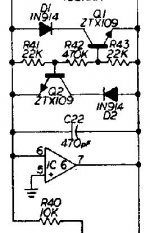
This is the real thing, open the attached .jpg in a new tab or window:
[open attachment below]
and simulate it if you wish, feeding it 10mV, 100mV and 1V 🙂
Attachments
Yeah, something is not quite right there, and I haven't figured out exactly what is going wrong. To be fair, I haven't put much time into it, either.Sorry but Nigelwright circuit is wrong 🙁 , don´t waste time on it.
Thanks for the circuit!This is the real thing, open the attached .jpg in a new tab or window:
I had to lower the 470k to 220k, otherwise there isn't enough voltage across the 22k resistors to turn on Q1 & Q2 at all, even with input level turned up until the op-amp output stage starts to clip at around +/- 13 V (with +/- 15 volt supply rails.) A quick voltage-divider calculation confirmed this.
Once R42 was lowered to 220k, the circuit does clip symmetrically, but in the simulator it seems to have the usual fairly abrupt-onset clipping typical of solid-state diode clipping circuits, i.e. it is not soft and progressive, but goes from completely clean at 0.2 V input to significantly clipped at 0.25 V input (which is less than +1 dB increase in signal level.)
I built dozens of diode and transistor distortion circuits similar to these in my twenties, and personally, I was disappointed with the results every time.
I came up with at least one design of my own that produced more progressive clipping than any of the typical diode clippers that have been around since 1960, but it didn't sound all that much better. My idea was a way to use multiple diodes and series resistors to lower the op-amp gain in small stages as the output voltage increased - a piecewise linear approximation to a smooth reduction in gain (something rather similar is used to shape triangle waves into sine waves in audio function generators.) It worked, but not as well as a plain-jane 12AX7...
-Gnobuddy
Attachments

So, battery experts---what if I buy NiMh batteries, install them, but leave the portable amp always plugged in via the AC adaptor, except when taking it out for outdoor jams? Then, I would (hopefully) have the batteries always charged and ready when needed. Would this work and be safe?
It will be safe. NiMh batteries do not explode. Worse case if severely overcharged, they vent making a stink not unlike a venting electrolytic cap.
NiMh does have a bit of a "memory effect" similar to NiCad, but not nearly as bad. This means that you should run them down to about 1 volt per cell once a month or so.
Constant charging without running the batteries down to 1 volt per cell occasionally will shorten their life or reduce their capacity. So will repeated partial discharging then recharging.
NiMh and NiCad can be slow charged, or rapid charged. Rapid charging involves a high initial charge current which is reduced to a lower rate after the cells begin to exhibit temperature rise. This can reduce cell life a little due to the heating drying out the electrolyte. It's best to slow charge only if fast charging isn't needed.
Slow charging involves feeding a constant current into the cell usually 1/10 of its rated capacity whenever the device is plugged in. As we learned with the laptops of the 80's and 90's, constant slow charge without ever discharging the battery will kill it slowly. If you play the little amp for some time each day or few days (more often than you would tend to need battery power) then only plug it in when used, or devise a method so that the battery only gets charged when the amp is actually used.
I plugged my laptop into a surge suppressor and only turned it on when I actually used the laptop. It outlived my coworkers laptops, but the battery still died after about 2 years. The constantly plugged in guys got about 1 year.
Well, these *are* "amplified diodes",the diodes being each transistor BE junctions.I had to lower the 470k to 220k, otherwise there isn't enough voltage across the 22k resistors to turn on Q1 & Q2 at all, even with input level turned up until the op-amp output stage starts to clip at around +/- 13 V (with +/- 15 volt supply rails.) A quick voltage-divider calculation confirmed this.
Once R42 was lowered to 220k, the circuit does clip symmetrically, but in the simulator it seems to have the usual fairly abrupt-onset clipping typical of solid-state diode clipping circuits, i.e. it is not soft and progressive, but goes from completely clean at 0.2 V input to significantly clipped at 0.25 V input (which is less than +1 dB increase in signal level.)
There´s no reason why these would sound "different".
The advantages are:
1) by varying the central resistor (220k in your example) you vary end to end clipping voltage at will.
Try it, turning it into a 220k pot ... you will smoothly clip from about 13V peak at maximum setting to some 650mV "1 diode drop" when set to zero.
Well, actually "2 diode drops" because you have an extra "fixed diode" in series each way.
2) by varying the BE resistors, making them different, you can make them clip in an assymetrical way.
Try doubling one of them 🙂
With that system you can generate any curve ... including what a 12AX7 does ... which is NOT smoothly rounding both peaks, by any means.I came up with at least one design of my own that produced more progressive clipping than any of the typical diode clippers that have been around since 1960, but it didn't sound all that much better. My idea was a way to use multiple diodes and series resistors to lower the op-amp gain in small stages as the output voltage increased - a piecewise linear approximation to a smooth reduction in gain (something rather similar is used to shape triangle waves into sine waves in audio function generators.) It worked, but not as well as a plain-jane 12AX7...
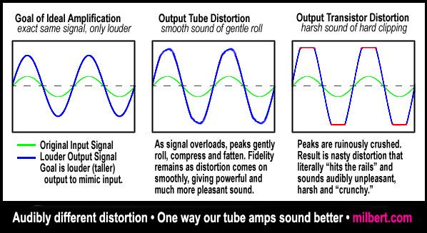
That´s a myth, spread by "gurus" and "typewriter designers" who clearly never bothered to scope a real 12AX7 🙄
This is a plain lie.
Notice these are *drawings*, not scope screen captures by any means 😎
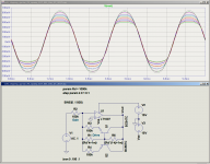
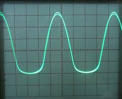
this is a scope image:
driven harder:

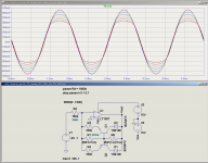
this is a heavily overdriven push pull Tube amp, no feedback pentodes:

Not exactly like the nice *drawings* in "Tube Books" huh?
Last edited:
this is a heavily overdriven push pull Tube amp, no feedback pentodes:
Not exactly like the nice *drawings* in "Tube Books" huh?
Looks like an 18 Watt.
I had a few discussions with people online on what a tube amp waveform looks like. A Bassman with its NFB does not look much different than a SS amp when over driven.
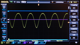
I'm attaching one of my own 'scope captures, this one from a small-signal "pentode" (which turned out to actually be a beam tetrode - a magnifying lens shows only four grid support rods and two grids.)this is a scope image:
Not exactly like the nice *drawings* in "Tube Books" huh?
It's interesting how triode saturation in your image is flattening the negative half-cycles of the signal, while lower pentode transconductance at lower anode currents is flattening positive half cycles in mine.
The initials KMG have come up in several diyAudio threads lately - he is a Russian electronics engineer who designed a circuit that takes an LND150 depletion MOSFET, along with several other active and passive components, and reproduces the waveforms from half-a-12AX7 quite accurately. I think I saw your name on one of his threads on the SS Guitar forum, so you are probably already familiar with his work.
-Gnobuddy
Attachments
I'm definitely not a battery expert. I know just enough to have "lithium paranoia".So, battery experts---
I will never forget the smell inside that Toyota pickup after the lithium pack fire - an absolutely vile combination of burned plastics and the stench of the flaming chemicals that came out of the Lipo pack itself. It's the kind of memory that lasts a long time, and makes a person cautious.
I tossed around the idea of just using twelve ordinary alkaline AA cells in series. That weighs less than the sixteen NiMh cells it would take to get about the same voltage, and there are no worries about charging. If the portable amp only gets occasional use, maybe it's an acceptable solution, and you never get stuck with a dead pack that needs a minimum of two hours to charge. The downside is replacement costs and the generation of even more waste for the recycling center, or worse, landfill.what if I buy NiMh batteries
I even did a little looking around for a small solar panel with enough grunt to keep a NiMH pack topped-up when used outdoors. Though solar panel prices on the industrial scale have fallen precipitously in the last few years, this doesn't seem to have trickled down to small consumer-sized solar panels. Or maybe I just didn't look in the right places.
-Gnobuddy
The only image I can see has its top & bottom chopped off, so I can't see all the components........Do you have a better one?Sorry but Nigelwright circuit is wrong 🙁 , don´t waste time on it. This is the real thing, open the attached .jpg in a new tab or window: [open attachment below]
and simulate it if you wish, feeding it 10mV, 100mV and 1V 🙂
I chopped off what´s not relevant 🙂 .
What you see is all you need.
You inject audio into the inverting input through the 10k resistor R40, you scope the Op Amp output, that´s all there is to it.
By the way, nigelwright´s circuit does not have much more than this ,just compare them side by side.
In fact, I guess he tried to test this one, but drew it from memory, and made a couple mistakes.
Please simulate it as I suggested earlier.
As of:
tube type is not that important, but designer´s choice of biasing, load, slope, etc.It's interesting how triode saturation in your image is flattening the negative half-cycles of the signal, while lower pentode transconductance at lower anode currents is flattening positive half cycles in mine.
- Status
- Not open for further replies.
- Home
- Live Sound
- Instruments and Amps
- Battery-Powered Princeton Reverb