Thanks Gnobuddy, that explains a lot.
I thought that it was caused by the series arrangement of the filaments, but it was not the case.
I think the current configuration of the output tubes already delivers a good amount of power.
To make it more bassman-like I will check the frequency response of the stages(through simulations, though) and compare to the original circuit.
Maybe one can get the same tone without the 400V plate voltages, maybe not...
Hi all, this is still on my list of projects, but I move much much slower than everybody else here with my projects, so I'm still just slowly accumulating parts.
On page one of this thread, PRR suggested going low voltage and low impedance with my output stage - rightly assuming that low output is my aim. To my shame, I ignored this suggestion, but I did so because I didn't understand the ramifications.
I was operating under the assumption that for a given plate voltage, and a given bias voltage, a lower primary impedance value results in a larger plate current, and thus higher dissipation/higher output. Now I keep reading that a lower impedance results in a lower output. I'm slowly connecting the dots - this is why PRR originally suggested using a low impendence for low output! But I just cant get my head around how that works. Can anyone please spare the time to enlighten me?!
You need to draw a loadline, corresponding to or derived from the plate impedance, into the set of plate curves. Roughly, the output power corresponds to the triangle area under this line. You'll find some certain angle between the loadline and the cathetus representing the plate voltage line that yields the power maximum. But obey the plate dissipation maximum hyperbola also!
Best regards!
Best regards!
Cheers Kay, this is my issue though - when looking at loadlines, using an imagined output transformer with a lower impedance results in a steeper plate load line than with a higher impedance. In the case of the 5672 tube, this means using quite a high impedance for a given voltage to get that loadline down under the maximum plate dissipation. This is why I don't understand, how does a lower impedance result in lower output? Or does it?!
Well, Merlin suggests the following equation to calculate the estimated power of a PP amplifier:
P = (HT-Vmin) * Ipeak / 2
HT is the high voltage, Vmin is the voltage where the load line crosses the 0 V grid line, I peak is the current where the load lien crosses the 0V line.
As your curve gets steeper Vmin increases, so you have less available swing (HT-Vmin).
A pentode also has curves that are almost horizontal. So, if you are above the knee, Ipeak will not change, only the difference HT-Vmin.
Now if your curve gets flatter, i.e. close to horizontal, the current drops, but the voltage swing is huge, but then, at some point, you will reach the voltage limit of the tube.
Going through the knee is normally one of the suggestions found in tube amp books.
Why are you using just one part of a 2-part suggestion?suggested going low voltage and low impedance ... assuming that low output is my aim.
I was operating under the assumption that for a given plate voltage, and a given bias voltage, a lower primary impedance value results in a larger plate current,
going low voltage
Sorry if I was being unclear, I do now intend to go lower voltage as well. What I'm trying to get my head around is - in isolation, does going lower impedence also lower total output and if so, how? Or was the suggestion a combination thing, lower voltage and thus lower impedence as well?
It depends on the tube you are using and the voltage you have chosen. But in general, a mismatch of the ideal impedance results in lower output.in isolation, does going lower impedance also lower total output and if so, how?
You are working with two resistances: transformer and plate (correct if I am wrong). If you mismatch the impedance, i.e. the transformers impedance does not match the plate's, it will result in a lower output.
So, going higher impedance beyond a point will also lower the output.
I think so.Or was the suggestion a combination thing, lower voltage and thus lower impedance as well?
If you go lower voltage (HT) you come closer to the region where the max. plate dissipation also goes up, so you can use lower impedances without destroying the tube(entering the region beyond max. plate dissipation).
As I said before, the highest output is normally associated with the load line passing through the knee of the 0 V grid curve.
At lower voltages the curve can be steeper, since the max. dissipation will be at higher currents (since the voltage decreased).
Sadly nothing to report in the build, 8 month old is taking every waking minute when I'm not at work!
I have accumulated parts if that's any fun to read?
Hammond 369HX power transformer. The 450V CT secondary will provide HT for the 12AX7's in the preamp, the 50V bias tap will provide a low HT for the output section.
And for a minor departure from the original plans, I'm switching from 5672's in the output section to the UK equivalent of the 1C5G. Not only can I pretend they are little EL34's (and I can use standard octal sockets), but it seems they can handle the preamp signal with less attenuation than the 5672's can, while requiring a more standard output impendence.

I’m watching with interest as I intend to build a Micro 6G14-A Showman using Rob Robinette’s beaten path with the Micro Bassman. I have already acquired a “16 ohm” JBL D130 driver and the pp output transformer (Edcor GXPP10-12K-4). Anyway, following along as you mull over your options has been informative and congratulations on the newborn. I have two myself, 15 and 6. They are the lights of my life.
There is a fundamental theorem of basic electricity that states that maximum power is transferred from a power source to a resistive load, when the load resistance equals the source resistance.What I'm trying to get my head around is - in isolation, does going lower impedence also lower total output and if so, how?
This theorem is at least 180 years old - a clever fellow named Moritz von Jacobi figured it out around 1840 or so.
If the load resistance is either too high, or too low, less power will be delivered to the load.
The reason is quite simple. The power source puts out its full voltage only when unloaded - but current flow is zero. Since power is the product of voltage and current, zero power is delivered to the (infinitely large) load.
Similarly, the power source puts out maximum current only when the output is shorted - but there is zero voltage across the (shorted) output, so, once again, there is zero power delivered to it.
If zero power is delivered to an infinitely large load resistance, and zero power is also delivered to an infinitely small load resistance, but finite power is delivered to in-between values of load resistance, then it follows that there must be a resistance value somewhere in between zero and infinity, to which maximum power will be delivered.
If you put Ohm's law and Kirchoff's laws together, and do a little algebra, and then a little differential calculus to find the maximum of the resulting equation, you can show mathematically that maximum power is transferred when the load impedance equals the impedance of the power source.
Lacking calculus, we can just plot the delivered power, and look for a maximum. An answer read off a graph isn't exact, but it's good enough for our present purposes.
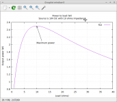
I did the math for you, and generated a plot using Gnuplot on my Linux PC.
(Gnuplot is a powerful program for plotting data or mathematical functions. It's free and open-source software.)
The attached image shows the result, for a 10 V DC source with a source resistance of 10 ohms.
Power delivered to the load in watts is plotted on the y-axis, while the load resistance is plotted on the x-axis.
As you can see, maximum power (2.5 watts) is delivered to the load when it has a resistance of 10 ohms - the same as the source resistance of the DC power supply.
The same result applies to AC power sources feeding resistive loads, too. If we replaced the 10V DC source with a 10V RMS AC source, we'd get exactly the same result.
Things are a little more complicated when the power source is a vacuum pentode - but the fundamental concept still applies. There is an optimum load, and if the load is too low, or too high, then it will receive less power.
-Gnobuddy
Attachments
You're right, basically. Anyway, if global voltage NFB is applied to a power amplifier, output impedance will be decreased by the NFB factor. This amplifier theoretically still WOULD provide maximum output power at a load impedance that equals it's output impedance, but other things do have a significant impact, such as power dissipation ratings, current capability of the PSU etc.
Best regards!
Best regards!
Any non-trivial Power Amplifier has several "output impedances". NFB can put Zout down to a hundredths of an Ohm for very small signals, or a naked Pentode/BJT amp may be >100 Ohms, but the power-transfer impedance may still be 3 Ohms. This is really more about power supply and output devices parasitic resistance than the circuit.if global voltage NFB is applied to a power amplifier, output impedance will be decreased
In isolation, there is no isolation. Look at the WHOLE circuit.in isolation, does going lower impedence also lower total output
Quite true, but also quite complicated. I tried to reduce my explanation to the simplest terms that would convey the most important message.Any non-trivial Power Amplifier has several "output impedances".
-Gnobuddy
I finished the amplifier I was working on. If you are interested:
https://www.instructables.com/Push-pull-Tube-Amplifier-Using-Subminiature-Tubes-/
Looks and sounds like another peach Thomas!
I've got a pile of parts waiting for me to get started at some point, but a toddler is the main priority these days, so I guess I'll get back to this in ten years or so! 😀
I've got a pile of parts waiting for me to get started at some point, but a toddler is the main priority these days, so I guess I'll get back to this in ten years or so! 😀
Just for posterity, my scope for this project has changed slightly from the title of the thread, but only slightly.
The idea now will be a regular 1987x Superlead pre amp section, so pretty similar to a Bassman/JTM. Rather than use sub-miniature output tubes, I quite like the idea of 'proper looking' (for the type of amp) Octal pentodes. So I have elected to go for a pair of 1C5G, or equivalent, battery radio tubes.
Playing around with some ideas, it looks like running them at around 50V I will be looking at an output of ~0.1W, which is about where I want to be.
I've seen that Celestion have come out with a low-sensitivity 12" speaker, the Peacekeeper, so I'll get saving for one of those - the combination should yield a peak SPL of around mid-70's dB, which is getting into the territory that I'm aiming for.
I too have changed course. I am doing an interstage transformer-coupled build using 1930s valves (1930s transformer bandwidth is sufficient for electric guitars) and a push-pull power stage using type 47 tubes. I’ll probably still need an 5-watt attenuator but it will be nice to have the ability to increase volumes if I get outside the apartment.
- Home
- Live Sound
- Instruments and Amps
- Bassman Micro - 5672 subminiature PP build