I forgot when doing my voltage dropping resistor calculations that there are two 5672s paralleled. Might be more like 27k, but, at this point, I advise against blindly trusting my calculations!
Digikey is one of the most reliable suppliers I've ever encountered, and they have this in stock: https://www.digikey.com/en/products/detail/pui-audio-inc/AS07808AS-R/9863637<snip>
Fostex FE83 3" Full Range is not cheap, and surely too good for guitar, but about 10dB less sensitive than "good" guitar speakers. SB Acoustics SB10???? 3" Full Range is similar at 1/3rd the price.
Frequency response looks very reasonably flat over the usable guitar range; it too will need a low-pass to knock down frequency response above 4 - 5 kHz.
Sensitivity is some 10 - 15 dB less than many guitar speakers, but that might be exactly what you want.
Classical guitar speakers don't have a flat frequency response, so you may need some sort of speaker emulation filter.
-Gnobuddy
I built a single-ended guitar amp a few years ago, with an output power in the range of 200 - 250 mW. Plugged into the stock speaker in my '65 Princeton Reverb reissue, it was amply loud for apartment use. A bit too loud, actually, when overdriven....I'm hoping/thinking that 0.1W should still be plenty loud?
I used the pentode section of a 6JW8 as the output valve. The 6JW8 is a 9-pin triode-pentode, with a 1.2 W maximum plate dissipation, but on a whim, I tinkered with the tube datasheet and found a 25k Fender reverb transformer and a roughly 135 volt supply rail worked out very well.
I used both the triode section of the 6JW8, and a 6AQ6 triode, as gain stages ahead of the little pentode. There was enough gain to go from clean to classic-rock.
The somewhat meandering road to the design starts here: https://www.diyaudio.com/community/threads/mini-amp-for-output-tube-distortion.326999/#post-5592850
-Gnobuddy
That approach has been used in a few expensive "active attenuator" designs as well, with a powerful solid-state amplifier following the dummy load resistor....Make your 1-2-4 watt output stage, whatever power, and overdrive it into a dummy load. DO this right inside the amp, then sample the now overdriven signal from the dummy load, and then feed THAT to a small amplifier you can adjust to the loudness you want to actually drive the speaker.
Having beaten a long, hard-fought path all the way to my own successful 0.2 W all-valve guitar amp, and having found that it too had its limitations, I agree with Enzo that there is a lot of merit to this approach. Valve amps have a "one size fits all" SPL when overdriven, which actually means "one size that never quite fits". So you almost have to add either VVR or some sort of adjustable speaker attenuator - or the re-amping solution Enzo suggested.
If you're flexible about your amplifier technology, after over thirty years of crappy predecessor products, for me, 2021 was also the year when truly affordable solid-state, modelling guitar amps using DSP finally reached the point where they sounded great - as good as many tube amps, better than some.
For instance, the Fender Mustang Micro blew me away when I heard this Cosmo Music demo, and it sold for only $100 USD at that time:
For most of this last year, my guitar rig has consisted of a Mustang Micro plugged into a little Yama mixer, along with vocal mics and a drum machine. The whole thing runs into a powered speaker used as a monitor, and a USB guitar cable that feeds the mixer output signal into a cheap little Raspberry Pi 4 computer, on which I run open-source Jitsi video-conferencing software for our online music jams.
For jamming at home, I plug the Mustang Micro into either headphones, or a little class-D power amplifier connected to a pair of thrift-store-refugee speakers that originally came from a Sony mini-HiFi.
Not too long after finding out about the Mustang Micro, I stumbled across Brett Kingman's demo of the Flamma Preamp:
As far as sound quality from a very affordable DSP guitar amp modelling device goes, that was another eye-opener, and the Flamma Preamp is less delicate and fiddly than the Mustang Micro - and it will work with your current guitar pedals. You can run the output into a flat-response powered speaker.
The Flamma Preamp is not designed to drive headphones, so I just finished building a tiny headphone amplifier in a guitar-pedal sized Hammond enclosure, starting with a postage-stamp sized Noisy Cricket evaluation board ( https://www.digikey.com/en/products/detail/sparkfun-electronics/DEV-14475/8702489 ). Now I can listen to it through either powered speakers, or headphones.
My headphone amp is powered by the usual 9 VDC power supply used by most guitar effects pedals, but I also put a little voltage regulator board inside the enclosure, set to supply only 2.7 volts to the audio amplifier board.
Running the Noisy Cricket board on only 2.7 volts reduces the danger of accidentally blowing out your eardrums or deafening yourself from excessively high SPL, by limiting output power to a few milliwatts into the usual 32-ohm headphones.
The fingernail-sized voltage regulator board I used is made by Pololu: https://www.pololu.com/product/2118
-Gnobuddy
Cheers, food for thought. I guess it boils down to do I use products that already exist and that are sensible or do I follow a path which is very unlikely to give me the end result that I want, but have fun along the way.
I have also tried a Yamaha THR10C, which I do like as a small and easy to use modelling setup, but found it frustrating that when it developed an issue (a slapback echo effect that stayed permanently on whether I liked it or not) there was very little I could do to remedy it. This little hiccup, albeit an isolated and probably rare problem, was enough to put me off modelling solutions for the time being.
I have my first child on the way shortly, so perhaps I just want this amplifier project as a bit of escapism!
Off topic, but I'm racing against time to build a guitar before the bambino arrives, I like the idea of playing entirely through things I've made.
My two cents: do whatever gives you the most enjoyment. Particularly in today's unhappy, COVID-raddled world, every bit of happiness one can scrounge is so important. And if that means DIY instruments and DIY low-power valve guitar amps, so be it! 🙂
Years ago, when I was the prototypical starving student, I built my own electric guitar, because I was too poor to buy one. It was made from scraps and bits and pieces, including a broken archtop acoustic guitar donated by a classmate, and pickups I made myself using bits of broken loudspeaker Ferrite magnet, plastic bobbins cut and glued from the little boxes in which my mom's typewriter ribbons were packaged, and metal strips cut from an old steel bed - with my mom's scissors!
It wasn't a great guitar, but it was all I had, so I played it anyway, for many years.
Your build looks great already. Is the shape of your guitar inspired by Brian May's own DIY Red Special?
-Gnobuddy
I just wanted to add that I've faced that question many times over the years....do I use products that already exist...
I started out building electronics at a very young age, 7 or 8 years old, using discrete components. My first "build" was a crystal radio with a single Ge diode. The next build included a PNP germanium transistor to amplify the very weak audio.
As the years went by, I progressed to building circuits using multiple transistors and dozens of discrete resistors and capacitors, and hand-designing and building my own PCBs for them
Then the first affordable audio ICs started to become available. I was faced with a quandary: for me, a lot of the fun was in designing my own circuits (which I'd been doing, to varying extents, since about the age of 10 or 11). An integrated circuit took that fun away from me, and instead put it in the hands of the person who designed the IC. Not only could I not see what was inside the IC, if the chip died, I couldn't fix it.
Eventually I realized that if I stuck with discrete-only circuits, I would be limiting myself in many ways. These newfangled integrated circuits kept getting better and better every year, and soon I could buy an entire audio preamp or power amp in a single chip. It was getting hard to justify having to cobble together a couple of dozen discrete components, only to achieve worse performance in a larger and more expensive package...
Years later, SMD components started to take over electronics, and newer devices were often entirely unavailable in through-hole versions. I didn't really want to start designing and soldering PCBs for SMD parts, or to deal with my aging eyes and parts so tiny that would be blown away and permanently lost in the carpet if I sneezed.
But then, companies like Adafruit and Sparkfun and Robotshop started to make "breakout boards" and "evaluation boards" that took a tiny SMD part, plopped it on a tiny PCB, and thus made it possible for the electronics hobbyist to use through-hole construction while working with SMD parts.
Once again, I had to adjust to the realization that even more of the creative part of the process had been snatched away from me, but at the same time, using these sorts of breakout boards allowed me to take my hobby where I could not otherwise go. And there was the enormous bonus of letting me continue to build projects quickly, even as my available free time shrank.
My most recently completed project - the little headphone amp I now use with my Flamma Preamp - is an example of this. I used a ready-made "evaluation board" with a little SMD stereo class-AB audio amplifier already completely built on it, along with another separate little breakout board containing a DC-to-DC converter to drop the 9V DC power supply down to 2.7 V for the headphone amp, limiting maximum SPL levels to less dangerous values.
Since all I had to do was figure out where to place all the bits and pieces in the little Hammond die-cast enclosure, and then drill all the holes, mount the parts, run the wiring, and solder everything up, it only took me one day to build the project, once I had all the parts in hand, and a few hours of free time.
I should add that I'm not trying to steer anyone else away from their chosen path to hobby happiness - merely mentioning that in exchange for adapting to the constantly changing world of electronics, one does get some rewards along with the loss of old preferences.
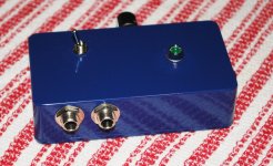
Here is a picture of my recently completed headphone amplifier. I don't love having the volume knob on the side of the (guitar FX pedal sized) enclosure, but that was dictated by the dimensions of the audio power amp breakout board, and the internal dimensions of the Hammond die-cast box.
The two 1/4" jacks are for left and right inputs - I can plug stereo FX pedals (like many reverbs) into this headphone amp. The little toggle switch is a mono/stereo switch - if driven by a mono pedal, flipping this switch to mono makes sure both headphones (L & R) are driven with the same signal, giving you a "double mono" soundfield.
The headphone output jack, and volume control, are on the far side of the enclosure. The green LED, of course, is a power-on indicator.
-Gnobuddy
Attachments
Fantastic! I'm almost as impressed that you manage to retain enough free time to enjoy your hobbies as the product itself! One thing that helps at this present time is the sheer amount of information that is available to help us along our chosen paths, and I am very grateful for that.
Without wanting to bore you about the guitar, it does indeed have a little 'Red Special' in it, but also a few other of my favourites like the Gibson Melody Maker and Les Paul Signature Bass, a bit of Fender Mustang and also Maton.
Without wanting to bore you about the guitar, it does indeed have a little 'Red Special' in it, but also a few other of my favourites like the Gibson Melody Maker and Les Paul Signature Bass, a bit of Fender Mustang and also Maton.
I concur with the sentiment, though the signal-to-noise ratio of technical information on the 'Net has been dropping steadily for at least the last two decades, maybe the last three....One thing that helps at this present time is the sheer amount of information that is available to help us along our chosen paths, and I am very grateful for that.
In the late 1980s and early 1990s, most people on the 'Net were actual scientists, engineers, and graduate students in engineering and science. There was much less information out there, for sure, but what was available, tended to be from authoritative and trustworthy sources.
In 2022, on the other hand, there are millions of people on the Internet who believe the earth is flat, or that 5G cellphones give you COVID-19, or that dual-cone "fullrange" speakers provide the highest quality audio reproduction. And they are not shy about sharing their bizarre beliefs online.
So there is an enormous and growing amount of misinformation out there now, and especially for newcomers, its getting harder and harder to tell the nonsense from the hard-won engineering and scientific realities discovered by generations of the most brilliant people.
There's a lot more gold out there than there was in 1990, but it's buried under a much deeper layer of excrement of the male bovine. One has to do a lot more digging to get at it. 🙂
Oh, that wouldn't be boring at all! I think building your own musical instrument is a fascinating thing to do. I hope you share more details, perhaps in a different thread on the appropriate diyAudio sub-forum.Without wanting to bore you about the guitar...
-Gnobuddy
Just to update this thread, I have gone ahead with an order for a Hammond 370CX PT and Hammond 125B OT.
In a wise move, I'm going to ignore all the useful advice I've been given and use the 50v bias tap half wave rectified for the output stage B+. The 370CX also has two filament windings, and one of these will be rectified for the DC filament supply for the output tubes.
As the icing on the cake for silly decisions, I've decided to audition two 5678 tubes in the output role. I will hilariously attempt this using the 125B's 1.5 Ohm secondary lugs connected to an 8 Ohm speaker, resulting in a planned primary impedance of around 144,000 Ohms. If this setup is just too quiet, I will try the 5672's. At least if it all goes wrong, it will be saved here for prosperity in case anyone else has this bright idea in the future. I have read that the 5678s are microphonic, so I'll dream up some way of trying to dampen them.
While I'm here, I have been wondering how on earth one goes about working out how much preamplifier signal needs dumping before the output stages? Is it just a case of using a master volume and going from there? Or do you try to work out how much gain is added to a typical guitar signal through each preamplification stage and compare that to the data sheets of your chosen output tubes to reach an acceptable looking signal voltage swing ?
It depends. Do you want some power stage distortion?
To me it sounds better than preamp distortion. It has a different harmonic content.
If you want a clean amp (is the Bassman a clean amp?) you need only enough to get full power at the output, which is comparable with the bias of the output stage. EL34 are biased at -40v, so you probably want more than 40v (peak-to-peak) to have some overdrive.
I biased the 5672 at -6v? I am not sure anymore... but I have at least 12v (p-p) from the preamp.
Let me show you my ultra low wattage amp:
I am familiar with that amp of yours, I have watched it quite a few times! I think it's cracking for a tiny amp, I would definitely like to try a variant of it. I also watch your MESA inspired amp on YouTube probably once a week for inspiration.
I am definitely aiming for power stage distortion, I would like to go non-master volume if I can. I am aiming for as close as I can get to a cranked JTM or Bassman as I can. They are not ultra high gain amps, but they are not clean amps either - just the right amount of distortion for me! I realise that with a completely different power section/OT/speakers, that it will never be identical, but at least with the same preamp circuit I have one variable that is the same. Maybe in the future I will try to emulate the whole topology with submini's.
I'm trying to get my head around around how to interpret the amount of signal strength required to get full output power from a tube and to go beyond this point for overdrive.
Say in the following chart for example, if I have picked a bias point (say -6v) and my plate (say 60v) and screen voltages, how do I know the signal voltage swing required for some distortion?
Is it in simple terms a case of having a signal voltage swing capable of driving the control grid up to 0V and beyond?
In which case, using a Bassman/JTM preamp section as is, without knowing the exact voltage swing to expect from the phase inverter, let's say for the sake of arguement that it's 50Vpp - for the case given above:
The positive voltage swing would be -6V + 25V = +19V
The negative voltage swing would be -6V - 25V = -31V
Well off the charts for the 5672 tube above, so I would expect to have to ditch maybe 75% of the signal from the phase inverter, meaning:
The positive voltage swing would be -6V + 6.25V = +.25V
The negative voltage swing would be -6V - 6.25V = -12.25V
Which looks more compatible with the charts. Am I in the right ball park?
As I understand it, the grid cannot go positive. 0V is the limit. At exactly +-6V you will have full output. If you increase it, it starts to hit the 0v line and distort. So you do want more than +-6 for distortion. The question is, how much more before it starts to sound fuzzy?
I am not sure what happens when you come close to the 0 current line, though. I guess you can go very negative, but the change in high voltage will be small once you are above a certain value (the lines get really close together).
I agree with you that by dumping 75% of the signal it looks better. You may want to drop less signal, so that you can check how much is too much.
Last edited:
As you and Thomasha have been saying, positive input swings have no effect at all once grid voltage reaches 0 V. The output tubes start to flow grid current, their input impedance plunges from nearly infinity to just a few kilo ohms, the phase splitter can't supply the requisite current, and even the input signal flat-tops....signal strength required to get full output power from a tube and to go beyond this point for overdrive.
Say in the following chart for example, if I have picked a bias point (say -6v) and my plate (say 60v) and screen voltages, how do I know the signal voltage swing required for some distortion?
But you will get some distortion well before clipping occurs. As you can see from the datasheet, the anode curves are quite unequally spaced, and get closer together both as you approach zero grid voltage, and also as you approach -12 volts on the grid. If you have reasonably good ears, this will cause subtle (but quite audible) amounts of distortion long before clipping occurs.
Guitarists will typically call this low level of distortion "clean tone". But in fact it has several percent THD, and this is what makes "clean tone" from a tube amp sound so much better than "clean tone" from a typical solid-state guitar amplifier. The SS amplifier will typically have 0.1% or less THD, which sounds too clean for guitar - thin, cold, lifeless, sterile, etc.
Okay. So much for subtle distortion. What about the other end of the curve?
My rough rule of thumb is to initially aim for a peak drive signal that's twice as big as the actual grid bias voltage. In other words, if your output grids are biased to -6V, aim for a 12-volt peak signal (24 Vpp) as a starting point. You can always tweak it from there by ear.
-Gnobuddy
It so happens that your rule of thumb is pretty much spot-on for the 5F6-a circuit. The bias voltage (according to the schematic) is -48V and the PI clips at about +95V on one side and +80V on the other into a 220kΩ load (grid leak value).My rough rule of thumb is to initially aim for a peak drive signal that's twice as big as the actual grid bias voltage.
Cool!
Do you think this might be coincidence, though, since supposedly Leo Fender never intended his Bassman to be overdriven?
I think the rule of thumb works well as a starting point. If the loadline for the output tubes is carefully chosen to go "through the knee" of the pentode curves, it gets me reasonably close.
-Gnobuddy
I'm sure it's a coincidence. As you said, the early guitar amps were not designed with overdrive characteristics in mind; it just so happens that many of them behave in a pleasing way when pushed.
Truthfully, I'm not a fan of the way early Fender designs - at least, the ones I've heard in person - overdrive. The use of negative feedback makes the overdrive less progressive, harsher, and more abrupt, and the big coupling caps and small grid stoppers encourage blocking distortion.
As popular music evolved to use more and more heavily distorted tones, it seems acceptance of overdriven classic Fender amp sounds has increased. In a recent Anderton's Music video about small tube amps, there are comments about how good the overdrive sound from a Princeton Reverb is.
-Gnobuddy
As popular music evolved to use more and more heavily distorted tones, it seems acceptance of overdriven classic Fender amp sounds has increased. In a recent Anderton's Music video about small tube amps, there are comments about how good the overdrive sound from a Princeton Reverb is.
-Gnobuddy
- Home
- Live Sound
- Instruments and Amps
- Bassman Micro - 5672 subminiature PP build