But of course it WOULD be overdriven. By accident or in anger.supposedly Leo Fender never intended his Bassman to be overdriven?
So does it get RUDE? Faint? Or just fuzz-up nicely?
Limiting to less than twice bias tends to avoid gross grid-blocking, which to a player may be the worst sin. (Play louder, amp craps-out, WTF??) Whether the number is 1.8 or 2.2 may matter to such as Neil Young, but that's another 10 years down the freeway.
It's a matter of personal taste, of course, but I find that many of the amps that I prefer the sound of (recorded, anyway) use some negative feedback in the power amp. The JTM45 sound is highly sought after by many and it uses gobs of NFB compared to most other guitar amps. NFB sharpens the transition between clean and distorted, yes, but that can be a good thing to some extent as it makes the amp more touch sensitive (easier to go from pretty clean to considerable distortion with pick attack). It can also prevent an amp from feeling excessively spongy if the power supply sags a lot.Truthfully, I'm not a fan of the way early Fender designs - at least, the ones I've heard in person - overdrive. The use of negative feedback makes the overdrive less progressive, harsher, and more abrupt, and the big coupling caps and small grid stoppers encourage blocking distortion.
I quite like some of the tweed amps (in sound clips anyway... I've not personally played one). Mostly the fixed-bias ones like the Bassman (5F6-a), Bandmaster (5E7), Twin (5F8-a), and Vibrolux/Harvard (5F10/5F11).
Blocking distortion is caused by too much dynamic bias excursion—too much of a good thing, in other words. Smaller coupling caps don't actually reduce bias excursion, they just shorten the time constant, making the blocking less obvious. Limiting the grid current with larger grid stoppers will reduce bias excursion.
That's exactly why that is my starting point. Tweak to taste from there....Limiting to less than twice bias tends to avoid gross grid-blocking...
I've used a MOSFET "source-o-dyne" phase splitter a few times. A MOSFET will saturate down to almost zero voltage (Vds), unlike a half-12AX7, which is reluctant to saturate to Vak less than 100 volts. The result is that you can get two antiphase 175 Vpp signals out of a MOSFET sourceodyne running on a 350 volt B+, before the MOSFET clips!
In that situation, dividing down the signals from the phase splitter before they hit the grids of the output tubes was mandatory. Otherwise there was such an enormous excess of overdrive available, that there was no way to avoid excessive amounts of blocking distortion.
-Gnobuddy
Agreed. I realized this, to my surprise, some years ago, while trying to design my first tube guitar amplifier.Smaller coupling caps don't actually reduce bias excursion, they just shorten the time constant, making the blocking less obvious.
The key metric turns out to be the ratio of grid bias resistor to grid stopper resistor. Imagine a hypothetical case where the grid stopper was 100k, while the grid bias resistor was only 10k. Even if the output tube is driven into grid conduction, that only puts a 100k resistor in parallel with the 10k resistor on positive peaks. Because 100k is ten times bigger than 10k, the increase in current draw during positive half cycles is rather slight.
More quantitatively, in this case, positive half cycles of current through the coupling capacitor are only about 10% bigger than negative half cycles, and this limits the amount of bias excursion that can occur.
A half-12AX7 is not happy driving 10k loads. If you raise the grid bias resistor value to 220k as Leo did, then you'd need 2.2 Meg grid stoppers to achieve this 10:1 ratio. This won't work - it exceeds datasheet maximum values for the grid bias resistor, and can potentially cause thermal runaway that destroys the output tubes (and maybe the output transformer with them).
Using a MOSFET source-o-dyne instead of a half-12AX7 cathodyne is one simple solution. It's easy to find a MOSFET that can drive a 10k load, and with 100% local negative feedback, there is no "tubey" distortion from a cathodyne, anyway, so replacing it with a MOSFET doesn't change the sound of the amplifier.
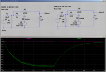
The attached image shows LTSpice simulations of the effect, which I originally put together when designing my little 2-watt 6AK6 push-pull amp. In the schematics, R2 is the grid bias resistor for the output tube, while R1 is its grid stopper. The diagram on the left uses typical vintage values of 220k and 1k respectively. C1 is the coupling cap from the PI stage, and was chosen to have a -3dB frequency of 33 Hz, well below the guitar's 81 Hz lower limit.
D1/V2 simulate how the output tube begins to flow grid current. In this particular case, output tube bias was about -9 volts, so V2 and D1 simulate the flow of grid current when the input voltage peaks reach 9 volts or bigger.
R3/C2 are a low-pass filter which filters out the 100 Hz audio component, leaving only the slowly changing (almost DC) bias excursion voltage, so we can see it more clearly in the simulation.
In the diagram on the right, the grid bias resistor (R5) has been decreased to 10k. The grid stopper (R4) has been increased to 100k. Coupling cap C3 has been adjusted to produce the same -3dB frequency of 33 Hz, so that changes in corner frequency don't corrupt the results of the simulation.
The green trace shows the tremendous amount of bias excursion that occurs if a prolonged loud note at 100 Hz is played.
The purple curve shows that bias excursion is dramatically reduced by the changes between left and right circuits.
Varying R5/R4 allows one to achieve the desired amount of bias excursion, according to the guitarist's taste.
-Gnobuddy
Attachments

Very nice explanation, I used some large grid stoppers before, but always discovered it through trial and error, by increasing it until there was no blocking distortion.
I guess there might be an equation for it in some book. Something new to check.
I guess there might be an equation for it in some book. Something new to check.
Thank you!Very nice explanation
I think you have very good ears (based on listening to sound clips from amplifiers you built). 🙂...I used some large grid stoppers before, but always discovered it through trial and error, by increasing it until there was no blocking distortion.
I don't know an equation that predicts the right value of grid stopper to just stop blocking distortion. But we can easily calculate something else - the biggest possible grid stopper that we can use. That can give us an upper bound.I guess there might be an equation for it in some book. Something new to check.
1) The first limit is that (R4+R5) must not exceed the maximum allowed value of the grid bias resistor.
2) The second limit is that R5, interacting with the input capacitance of the output tube, must not affect the high frequency response of the guitar amplifier.
Since there is nothing good in electric-guitar sound above roughly 5 kHz, I usually pick 10 kHz for this.
For example: let's say our output tube has 3pF input capacitance (from the datasheet). Let's suppose our tube socket and wiring adds another 7 pF to that, bringing the total up to 10 pF.
Since f(3dB) = 1/(2 Pi R C), we can calculate that the maximum value of grid stopper we can use is 1.59 mega ohms (!)
Bigger pentodes have more input capacitance, but it still tends to only be a few pico farads. And that means we can use really big grid stopper resistors without harming treble response. Usually limit (1) kicks in before limit (2) does.
Between (1) and (2), we can usually pin down reasonable starting values, and then tweak from there by ear (or with the 'scope).
-Gnobuddy
Last edited:
So, I was trying something myself:
Battery powered (I need another desk amp...), with 4x5678 and 2x5672.
I used the curves for a screen grid voltage of 90v. Bias should be -11v, but with the batteries fully charged it got up to -12v.
The transformer is a 100V line transformer, where I'm using the 0, 2.5W and 0.625W taps. Should give a 16k primary, but I am connecting the 8 ohms speaker to the 4 ohms tap, to get 32k (16k class A and 8k class B, see curves below)

I thought it would be too low gain to use a complete tone stack, so I went for a single tone control, connected to the gain pot. The lowest loss possible.
Turns out this thing has enough gain...
First stage amplifies 0.2V pp(peak to peak, used a sine wave with 850hz) to 2.5V pp, second stage already distorts...So, for the video I reduced the gain knob to get a clean signal at the paraphase input. 4th tube has a trimpot to adjust the input (should be equal to the input of the previous stage). I also measured the voltage at the grid of the 5672, I think it was roughly 12V on one and 12.5V on the other, so still slightly off.
About the bias, I am powering the filaments in series, so every negative side also has a 220uF cap to decouple any signal, otherwise there is a lot o feedback.
According to the datasheet, bias should be measured considering the negative side of the filament, so the cathode voltages (f-) are:
0v, 1.2v, 2.4v, 3.6v, 4.8v and 6.0v dc (ideally, things are a little higher with fully charged batteries). To get the bias correct I use the ICL7660S to invert the 7.2v to -7.2v and have a series string for the grids. The grid voltages are:
-1.4v, 0v (gnd), 1.2v (second f-), 2.4(third f-), -6.2v and -5v. (Theoretically)
As you can see, only 3 stages really need the ICL7660S bias. The resulting bias is:
-1.4v, -1.2v,-1.2v,-1.2v, -11v, -11v (if I am not mistaken)
Measured values are:
-1.52v, -1.45v, -1.62v, -1.68v, -6.22v, -5v with batteries at 8.2v
In the schematic I changed the series string, so that the first stage (most sensitive to noise) will not be connected to the ICL7660S. There is room for improvement.

Anyway, now I can trim some gain here and there, adjust some stuff and maybe it works.
Battery powered (I need another desk amp...), with 4x5678 and 2x5672.
I used the curves for a screen grid voltage of 90v. Bias should be -11v, but with the batteries fully charged it got up to -12v.
The transformer is a 100V line transformer, where I'm using the 0, 2.5W and 0.625W taps. Should give a 16k primary, but I am connecting the 8 ohms speaker to the 4 ohms tap, to get 32k (16k class A and 8k class B, see curves below)
I thought it would be too low gain to use a complete tone stack, so I went for a single tone control, connected to the gain pot. The lowest loss possible.
Turns out this thing has enough gain...
First stage amplifies 0.2V pp(peak to peak, used a sine wave with 850hz) to 2.5V pp, second stage already distorts...So, for the video I reduced the gain knob to get a clean signal at the paraphase input. 4th tube has a trimpot to adjust the input (should be equal to the input of the previous stage). I also measured the voltage at the grid of the 5672, I think it was roughly 12V on one and 12.5V on the other, so still slightly off.
About the bias, I am powering the filaments in series, so every negative side also has a 220uF cap to decouple any signal, otherwise there is a lot o feedback.
According to the datasheet, bias should be measured considering the negative side of the filament, so the cathode voltages (f-) are:
0v, 1.2v, 2.4v, 3.6v, 4.8v and 6.0v dc (ideally, things are a little higher with fully charged batteries). To get the bias correct I use the ICL7660S to invert the 7.2v to -7.2v and have a series string for the grids. The grid voltages are:
-1.4v, 0v (gnd), 1.2v (second f-), 2.4(third f-), -6.2v and -5v. (Theoretically)
As you can see, only 3 stages really need the ICL7660S bias. The resulting bias is:
-1.4v, -1.2v,-1.2v,-1.2v, -11v, -11v (if I am not mistaken)
Measured values are:
-1.52v, -1.45v, -1.62v, -1.68v, -6.22v, -5v with batteries at 8.2v
In the schematic I changed the series string, so that the first stage (most sensitive to noise) will not be connected to the ICL7660S. There is room for improvement.
Anyway, now I can trim some gain here and there, adjust some stuff and maybe it works.
The guitar is very badly out of tune. 🙁So, I was trying something myself:
-Gnobuddy
Hey fantastic, I know you're still tweaking it but I really like what you have so far. Are you happy with it? What changes are you thinking of making?
So, I tested it again with a sine wave with 0.2 vpp (0.068 vrms) and 850Hz and made some measurements (voltages read from cheap oscilloscope, as in the video, so it may vary a bit) and observations:
- Clean signal produces 3.0vpp or 1.04 vrms with a 8 ohms speaker.
- Preamp distortion is visible when the signal at the power tube grid reaches 26vpp, or 9vrms. At this point power tubes are already distorting.
- With gain (volume) maxed signal at the power stage grids is around 41.0vpp or 18.12vrms, which explains the fuzz at higher settings.
I was thinking about it, and I would limit the signal at the grids at 20vpp. Since the highest level is 41vpp, I can dump half of the signal just in front of the power tubes. This way I will have preamp distortion before the power amp starts to distort.
Or I can add a tone stack after the 2nd stage. This would reduce the signal, reducing the preamp distortion and the signal arriving at the power tubes. I guess this is what the bassman does. Maybe I still would need to drop some additional signal.
For the time being I'm enjoying the highly distorted amp.
- Power distortion starts before preamp distortion, when the grid of the power tubes reach 18.7V (visual inspection of the wave deformation, not 100% accurate...)
- To measure at the OT I had to use a voltage divider (1M and 10k) in front of the oscilloscope. By extrapolating the measurement based on the ratio seen at the grid (I am neglecting the different loads here...) it should swing about 159vpp or 58.4vrms. It seems, considering the load line, that it already reached class B.
- Clean signal produces 3.0vpp or 1.04 vrms with a 8 ohms speaker.
- Preamp distortion is visible when the signal at the power tube grid reaches 26vpp, or 9vrms. At this point power tubes are already distorting.
- With gain (volume) maxed signal at the power stage grids is around 41.0vpp or 18.12vrms, which explains the fuzz at higher settings.
I was thinking about it, and I would limit the signal at the grids at 20vpp. Since the highest level is 41vpp, I can dump half of the signal just in front of the power tubes. This way I will have preamp distortion before the power amp starts to distort.
Or I can add a tone stack after the 2nd stage. This would reduce the signal, reducing the preamp distortion and the signal arriving at the power tubes. I guess this is what the bassman does. Maybe I still would need to drop some additional signal.
For the time being I'm enjoying the highly distorted amp.
Well, the cleans sound nice, there is also a nice distortion right at the beginning, around 10 o'clock. From this point on it gets nasty, but with the gain pot maxed (more bass) it sound like a nice heavy fuzz. So I am going to reduce the available gain to only get the behaviour of the gain pot between 7 and 10 o'clock.Hey fantastic, I know you're still tweaking it but I really like what you have so far. Are you happy with it? What changes are you thinking of making?
The PI also needs some changes. In the current configuration the gain is not equally distributed once it starts to distort. The first triode distorts and then it gets a lot of attenuation and goes to the second triode, which distorts the other side of the signal.
Hi,
in the last two days I did some measurements and some changes.
First, the schematic does not match the build, since I used available parts.
- Just found out that R11 instead of 51k (80k in the schematic) was 510k (ouch!).
- R17 and R14 were replaced by a trimpot (1M). It reads 0.874M though. On one side I have 0.824M and on the other 88.1k. So I'm guessing there is a measurement uncertainty here... I think a ratio of roughly 10:1 is what I need here. I would keep the trimpot, but at lower value for finer tuning.
- R11 is 680k instead of 470k. In my new test I added a pot here to reduce this resistor until I got the max. distortion I wanted (24V at the grid of the power stage). The ideal value is more like 41k, which drops a lot of signal.
The measurements gave a better understanding o the amp. Considering the 0.2Vpp and 850hz signal I had some findings:
- The preamp (two first stages) will never distort no matter what. With the gain pot and grid stopper the signal at the grid is roughly 2.25Vpp in the worst case. With a bias of -1.68V it would require more than 3Vpp to distort the second stage.
- The power amp distorts first, when the grid has a signal with 13.5Vpp, resulting in 2.8Vpp at the speaker. This is strange, since the bias is -11.8V (considering f- voltage and grid bias voltage). It should distort much later (>20Vpp), shouldn't it? At this point I had a lot of questions...
1- Why is it already distorting at 13.5Vpp? (-6.75V bias?). It probably starts earlier, I just can't see it without a proper oscilloscope. The f- pins are at 5.6V and 6.8V, while the grids are at -6.2V and -5.0V, resulting in the -11.8V bias.
2- What happens with the extra current (2.5mA idle, 8mA at 0 grid, according to diagram), when the filaments (and cathodes) are in series? Should I add another resistor to ground to allow some of the current to escape, since the previous tubes will all have idle currents lower than 0.5mA?
I tested adding a 2.5K and 3k resistors (2.5mA) to each f- and guess what...the clean shifted a little bit. Checking the signal at the speaker, the same wave shape (clean-ish) could be observed up to 3.3Vpp. Forgot to measure the grid voltage swing, but I increased the gain to get to this value. Not certain if I should add a smaller resistor to allow more current to flow (8mA) to account for the worst case, since it also loads the series string (filament voltage varied about 0.1V). I still have to think a way to test it and see if it really makes a difference. Unfortunately, battery tubes are not usually used in this way. The simplest thing would be to add another battery.
- The distortion seen at the grid of the power tubes actually comes from the paraphase PI, which is a normal gain stage (without the feedback resistor and unity gain). It actually multiplies the signal at the input about 10 times. The first tube in the PI (V3) starts to distorts at 2.5Vpp, the distorted signal goes to one power tube with 30.6Vpp and to the second tube of the PI (V4), where the value was 2.35Vpp. This tube amplifies the signal to the other power tube, with a little less signal (27.6Vpp). The differences in voltage is a result of a non-perfect adjustment of the trimpot (1M). With lower trimpot values it should be easier to adjust.
Here you find another video:
The noise in the beginning comes from the MAX1771 SMPS. Unfortunately, in this kind of open build everything is pretty sensitive to noise. I tried shielding the MAX1771 chip, the Inductor and the whole board, but I couldn't get rid of the strange noise. I even added a low pass filter, but it only changed the frequency of the noise. I think the Max1771 is not very friendly in this case. The load is also too low, I will end up using the 555 SMPS anyway. Obviously, that when everything is inside a metal box with the sensitive spots close to ground planes it should be solved.
The amp is quite bright with the tone pot on half. There are plenty of tone shaping possibilities here. If you have any suggestions regarding the schematic or changes, please let me know.
Visaton TR 10.16.
Now that you ask I might have used the wrong tap for the centre tap, according to the impedance chart. The number of turns, on the other hand, says the contrary…weird
Now that you ask I might have used the wrong tap for the centre tap, according to the impedance chart. The number of turns, on the other hand, says the contrary…weird
It seems, the winding ratios I had were for the TT IZ 1892 and not the TR 10.16. Unfortunately I could not find any values for the TR 10.16 other than the impedances.
The windings of the TT IZ 1892 are: 725+300+400+600+900 and for the secondary 48+18+30.
If both transformers are similar, the 0-2.5W tap would have 1425, while 2.5W-0.625 would have 1500. Slightly off, but only marginally.
PS.: Never mind, the impedance in SE does not translate to the impedance in PP, so the centre must be 2.5W.
Same here, but I think you are quite correct. Half the winding ratio in a transformer, produces one-fourth the impedance ratio, which means four times the power delivered to the speaker....Unfortunately I could not find any values for the TR 10.16 other than the impedances.
So "common" and "0.625 W" connections are the full primary winding. Four times as much power - 2.5 watts - is the centre-tap. Exactly as you said earlier.
I wouldn't worry about how perfectly (or not) the two halves are matched. For starters, the two output tubes will never be perfectly matched, either. More importantly, perfect matching would cancel out all even harmonics, and that does not necessarily produce the best timbre (depending on your musical preferences.)
Many years ago, I had the idea to deliberately imbalance the phase splitter to allow some even harmonics through. When I Googled, I found that others had had the same idea long before I did. I found an Australian amp design that had a knob to dial down one output of the cathodyne PI, all the way to zero, so the output could go from push-pull all the way down to single ended.
Another diyAudio member (Bob Richards, I think) also had the same idea long before I did, and he things very scientifically. He used an actual lab-grade hardware spectrum analyzer, and found that a one-decibel imbalance in the two phase splitter outputs was sufficient to bring back the rich single-ended tone he preferred, while preserving most of the efficiency and power output benefits of a push-pull output stage.
One decibel is the same as 12.2 %, by the way. If one PI output is about 12% bigger than the other, you get about the right amount of imbalance (if the output tubes and OT are perfectly balanced, which they never are!)
I like your simple PCB oscilloscope. It is the Elektor / JYE Tech DSO 138, isn't it?
The waveforms on your 'scope look much cleaner than my Rigol 1054Z, which cost me four times as much. The Rigol has much more bandwidth and 4 channels, and a nice housing, and many useful features if you're working with digital signals. But it's disappointing for audio use - it has very poor vertical resolution (only 8 bits), and the screen has only 480 pixels in the vertical direction. Between those two severe limitations, audio waveforms look very bad, with big, jagged, ugly "stairsteps".
Personally, I'm only interested in guitar electronics measurements, which means audio frequencies that never go higher than 10 kHz. So I don't need 50 MHz bandwidth like my Rigol has, but I would like at least 10 bit vertical resolution, which gives you 1024 vertical steps, good enough for even a 1080p HD display.
The original DSO138 has 12-bit vertical resolution. Vertical steps are sixteen times smaller than the 8-bit ADC in my Rigol. No wonder the audio waveforms look better on the DSO 138!
I may have to build my own oscilloscope one of these days. An Arduino Due has a 12-bit ADC onboard, and it is very fast, more than fast enough for what I want.
-Gnobuddy
Exactly. For the Visaton TR 10.16, common and 0.625 watts are the plate terminals, 2.5 watts is CT.
Best regards!
Best regards!
Hi,
this weekend a tried to test different configurations to see if I could get a little extra signal out of the PP 5672, and verify why it distorts already at +-14Vpp instead of 24V (2x-12V, the bias voltage). Therefore I tested 3 configurations:
1. Series filament string with specific bias at every grid
2. Additional 1.2V battery for 5672, with f- at ground and grids at -12V
3. Additional battery 1.2V battery for 5672, with f- at 12V and grid at 0V
Apparently, it makes no difference. It will always distort at the same level.
I verified the PI, to look for some unbalance, but both 5672 get approx. 13.4Vpp at the grids. There might be some influence due to the input impedance of the oscilloscope, though. It might load the stages differently.
The PI I use here is a mere extra gain stage with a trimpot to adjust the input level, so that both output tubes see the same signal. I might give the feedback resistor seen in some paraphase PIs a try.
Good news is, that it looks better at -12V than at -7.2V (2xLiPo), so the extra bias circuitry is totally worth it at the given plate voltages (90V).
I also managed to model it in LTSpice. The simulation gives a good Idea of what happens, and the signal at the output stage is already strongly affected by the previous stages, presenting a slight change in shape, where it starts to look more like shark teeth than a perfect sine wave (I am guessing this is due to phase changes).
It helps to quickly test some changes. One thing that I still have to try is how to add negative feedback to this circuit, since I cannot use the cathodes for that. My best results so far are injecting the signal at the grid of the first PI tube. I still have to tweak with resistance values, otherwise it drastically reduces the output signal.
PS.: The first tube might be very susceptible to microphonics due to the amount of gain and its construction. Some suggestions I found that deal with it, instead of tossing the tube, consisted of damping the tube socket (here the tube itself, since it's soldered to the circuit) or adding a 100pF plate bypass capacitor. I would suggest doing this to the first stage, otherwise it will whistle sometimes.
Cheers,
Thomas
Last edited:
Some reasons for this are in the attached image.Apparently, it makes no difference. It will always distort at the same level.
The green dots I added to your load line are very unevenly spaced, and cluster together towards the top left corner (near the Vgk=0 end of the load line). This means plenty of audio distortion long before the Vgk reaches zero volts.
Each anode (plate) will rise well above the 90V B+ as the corresponding valve approaches cut off. It would be interesting to extend the graph to the right, up to 180 volts, and see what the blue load-line does in that region. (It looks like the tube curves and green dots will also be squeezed together as you approach cut off, causing distortion at that end of the load line as well, and again reducing the range of Vgk for (relatively) undistorted operation.
-Gnobuddy
Attachments
- Home
- Live Sound
- Instruments and Amps
- Bassman Micro - 5672 subminiature PP build