Gareth,
From memory I can try to share my experience about a few of the P10 Mini-Onkens I have built/heard (Mar-Ken7.3, CHR-Ken70, CGR-Ken70, CGR Mar-Kel70) - the bass articulation and imaging - both were very good. Suitably placed in the room, they can give decent extension for a cabinet of that volume with a modestly sized driver. No experience with the Alpair 10.3 in a Mini-Onken though.
From memory I can try to share my experience about a few of the P10 Mini-Onkens I have built/heard (Mar-Ken7.3, CHR-Ken70, CGR-Ken70, CGR Mar-Kel70) - the bass articulation and imaging - both were very good. Suitably placed in the room, they can give decent extension for a cabinet of that volume with a modestly sized driver. No experience with the Alpair 10.3 in a Mini-Onken though.
Member
Joined 2009
Paid Member
Thanks Zia, good to know. I had not considered this project until my friend said he wanted me to move my big floorstanders to do some listening tests on a new DAC and I thought about a smaller speaker being easier - I built some Pencil's for him many years ago and he's recently changed out the 10.3 drivers for 10p. He prefers the 10p because it doesn't suffer from the rising on-axis treble of the metal driver. So this is why the 10.3 drivers are now available to me. They are well run-in already.
What's the thought on the necessity for rounded or beveled cabinet edges to avoid diffraction messing up the imaging ?
What's the thought on best place to have the port (front, rear, bottom) ?
What's the thought on the necessity for rounded or beveled cabinet edges to avoid diffraction messing up the imaging ?
What's the thought on best place to have the port (front, rear, bottom) ?
What's the thought on the necessity for rounded or beveled cabinet edges to avoid diffraction messing up the imaging ?
What's the thought on best place to have the port (front, rear, bottom) ?
The P10 Mini-Onken's have multiple resistive ports at the front and on both sides of the cabinet, while the CGR-Ken's have their ports near the bottom of the cabinet - both work fine. The P10 Mini-Onkens probably "disappear" in the room slightly better vs the CGR Kens because of the wide round-overs on the baffle. With the wider front baffle of CGR-Ken's you can slightly offset the driver (don't think I did that) to improve diffraction; that ways you will have to build "mirror imaged" pairs.
Member
Joined 2009
Paid Member
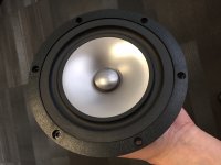
drivers look to be in good condition still...
Yes, looking like new. 🙂
Member
Joined 2009
Paid Member
Well, the workbench and saw are in the garage, it's unheated and this is Ontario in the winter, so this will be a labour of love!
For further punishment - because it would be more work - but I could have a go at using thin side / top / bottom panels with bitumen damping stuck on the inside - kind of 'BBC esque' with regular thick front baffle and rear panel.
Thoughts ?
For further punishment - because it would be more work - but I could have a go at using thin side / top / bottom panels with bitumen damping stuck on the inside - kind of 'BBC esque' with regular thick front baffle and rear panel.
Thoughts ?
Same as Dave. The BBC style of thin-wall construction can work well if properly done (it's not just a matter of making thin panels and attaching bitumen to them), but I prefer the high rigidity approach to avoiding audible panel resonance. It's usually easier and cheaper to achieve, and in some cases will provide the drivers a stronger overall structure to work against.
Member
Joined 2009
Paid Member
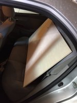
Thanks guys, I'll take that advice. At least as far as practical - my little car doesn't handle large sheets easily and I ain't driving around in winter with the back open and seats folded down so I brought back a 'handy panel' of half-inch birch plywood.
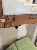
Whilst taking it out of the car and stowing in the garage I found a hole in the dry wall. Around the hole are some long brownish animal hairs - and given that a particular local animal has been very active around my house and roof line by the garage I am concerned that there's a darn bloody squirrel in my house somewhere !!!! 😱
Whilst taking it out of the car and stowing in the garage I found a hole in the dry wall. Around the hole are some long brownish animal hairs - and given that a particular local animal has been very active around my house and roof line by the garage I am concerned that there's a darn bloody squirrel in my house somewhere !!!! 😱
Attachments
Member
Joined 2009
Paid Member

It's darn chilly, trying to saw wood in between warming hands.....
The joys of DIY! 🙂
How's the cutting coming along?
Member
Joined 2009
Paid Member
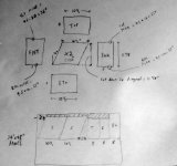
I had this idea that the front panel should slope back a bit so that I'm not listening directly on-axis. I chose 10 degrees because it seemed to fit nicely into my cutting plans. I know you can do some toe-in or toe-out to point the axis away from the listening chair but that works best when there's only one listener. When you toe-up (or tilt back) it's possibly better for those times when there's a few more folk. Then I thought it might look a bit odd if the back wasn't parallel to the front so I tilted the back. Then I thought it would be nice if the joints were all mitred so it was a bit neater. Well, it was a nice idea but it does add a bit more work to the simpler Woden design I started out with. Anyhow, I made some progress, got the main pieces cut and got most of the mitres cut. There are some mitres that have to be cut at non 45 deg angles (actually, 35 deg and 55 deg) and this requires some extra effort because my saw only goes from 0 to 45 so I'll have to cut the 55 deg angles with the wood on edge. Of course there were a couple of mistakes made during all this messing around and they were remedied by cutting off a bit of wood here and there, like the barber who keeps trimming the hair shorter and shorter to get it all lined up; so the final volume is going to be less than the starting point too. All for fun. I'm off on business travel tomorrow so will finish up the sawing when I'm back. Then it'll be time to pull out the router thingy.
Attachments
Last edited:
Member
Joined 2009
Paid Member
I was nearly there!
I did dry-fit of all the pieces but there were still some inaccuracies that will prevent it from going together cleanly and I'll not be happy with a rough job of it. So I decided to clean it up by running some of the pieces back through the saw. However, it's not as easy as I thought, it will take more time to do a proper job of it - I think some adjustments to the design will make it far easier to do a good job of it. So, great fun so far and a lot of valuable insight gained. Instead of trying for 12 edges of odd angle mitre joints I'd go for mitres on only the critical edges, butt joints on the rest where they won't affect my cosmetic goals. I'd avoid any mitre cuts that are not 45 degrees so that when using the saw I have the easiest time holding the workpiece for best accuracy and repeatability.
I did dry-fit of all the pieces but there were still some inaccuracies that will prevent it from going together cleanly and I'll not be happy with a rough job of it. So I decided to clean it up by running some of the pieces back through the saw. However, it's not as easy as I thought, it will take more time to do a proper job of it - I think some adjustments to the design will make it far easier to do a good job of it. So, great fun so far and a lot of valuable insight gained. Instead of trying for 12 edges of odd angle mitre joints I'd go for mitres on only the critical edges, butt joints on the rest where they won't affect my cosmetic goals. I'd avoid any mitre cuts that are not 45 degrees so that when using the saw I have the easiest time holding the workpiece for best accuracy and repeatability.
I recently got hold of a set of 10.3s from Finland that i put into my BR boxes that were left over after i built Pensils for my enabled 10ps. This weekend i had some spare time and got to changing the reflex port to the specified length for the 10.3s and decided these should have some nice, custom speaker stands as well.
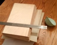
I did a rough outline in sketchup. Only the dimensions of the top and bottom plates are fixed, and the top plate is the same dimensions as Scott's box. I cut the wood in a local hardware store that has a hobby workshop (i don't have space for storing or working with miter saws etc at home), and was dependant on their limited supply of wood. Both top and bottom plates are 18mm BB ply that i found a nice offcut of with the right amount for both plates ($8 total). The large beams are rafters for roofing, and the smaller pieces 12mm BB ply (also offcuts). Altogether, they came to less than $50, including the dry sand used to fill them (10kg each).
The large roofing beams were quite warped, so the whole pillar construction has a slight pitch to it, but i feel like i managed to hide that reasonably well by aligning the straight part with the bottom plate and having the less straight bit under the top plate. I added a few screws to help the glue hold things together, as they are very heavy! I will sand and laquer them to match the wood of the speakers, and make the end pieces of the baseplates show the layers of the ply a bit better.
In time, i also plan to raise them a bit further by installing spikes underneath. I have some M6 threaded nuts i want to install under each bottom plate, but i am still working on the best way to make sure these are inserted nice and straight. A size 10 drill gives a hole that is large enough, but the nuts are very difficult to align totally straight - suggestions are welcome!
Altogether, new life for these BR boxes. The drivers are still in the break-in stage, but i've been listening at low volume and am really looking forward to more listening and comparisons with the 10p Pensils. Now i just need to build a new room to put them in...
Attachments
-
 Photo 26-02-2019, 17.07.57.jpg485.6 KB · Views: 141
 -
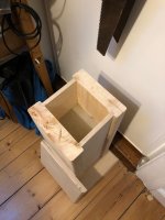 Photo 26-02-2019, 17.08.24.jpg398 KB · Views: 131
 -
 Photo 25-02-2019, 21.52.08.jpg320.9 KB · Views: 135
 -
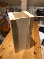 Photo 25-02-2019, 18.24.12.jpg226.5 KB · Views: 138
 -
 Speaker stands_1.png39.7 KB · Views: 134
 -
 Photo 26-02-2019, 21.57.34.jpg368 KB · Views: 179
Last edited:
Good work silasmellor.
Am I right in assuming that you want to get your threaded nuts inserted dead straight for (1) aesthetic reasons (2) to get contact on all four spikes?
If you use three spikes per stand, you will always get contact on all three points; but not sure if the stability will be the same. I've seen some folks use three spikes for their speakers.
Thanks zman  yes, both reasons. Dead straight will definitely be better for my ocd. I’ve got some nice soundcare feet I want to use, 4 for each and I am a bit wary of 3 per stand :s strictly speaking I am not sure they really need to be dead straight, so my OCD is probably the main issue at play here 😀
yes, both reasons. Dead straight will definitely be better for my ocd. I’ve got some nice soundcare feet I want to use, 4 for each and I am a bit wary of 3 per stand :s strictly speaking I am not sure they really need to be dead straight, so my OCD is probably the main issue at play here 😀strictly speaking I am not sure they really need to be dead straight, so my OCD is probably the main issue at play here 😀
Not uncommon in DIYers! You need to make it is good as possible, right? 😀
- Home
- Loudspeakers
- Full Range
- Bass reflex standmounts 10.3 / 10P