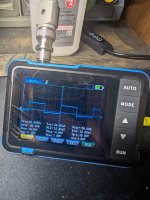
You need to leave your scope on DC coupling. It's virtually never good to have a handheld scope on AC coupling.
Set the scope to DC coupling and see what you have on both terminals. It won't be the same on both sides of the cap.
Set the scope to DC coupling and see what you have on both terminals. It won't be the same on both sides of the cap.
Okay noted. I'll check again after eating quick.
So always use the scope on DC coupling regardless of what I'm probing then?
So always use the scope on DC coupling regardless of what I'm probing then?
With a battery powered scope, you will leave it on DC. If you're checking drive signals where you might want to use AC coupling, you place the scope ground on the source terminal of the FET and then probe the gate.
For mains powered scopes with grounded inputs, you cannot directly connect to the source with the scope probe ground. You have to use differential mode. Not hard to do. I leave my scope always set for differential input. It doesn't change the way the scope works but you can check drive waveforms with proper DC coupling, even for the high-side.
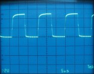
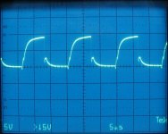
Below, the high-side in normal mode (20v/div) and in differential mode (5v/div). In normal mode, you can't tell anything. In differential mode, you can see the actual high-side drive. The DC coupling lets you see that the drive is pulling back to 0v. It's absolutely critical that you can see that it's going back to ground (or at least very well below the FET's threshold).
Attachments
Last edited:
23.8v on input and 15.1 output with remote power switched on, sorry for the confusion I went back and edited the comment.
Please DO NOT give values without remote.
On R173. DCV on each end with black probe on ground WITH REMOTE.
On R173. DCV on each end with black probe on ground WITH REMOTE.
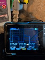
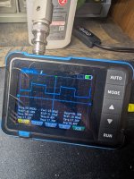
Also reading 15.18v. Dmm is accurate, apparently my scope is still way off even after calibration. I apologize. Will be looking for a better scope ASAP
It should be noted that at the beginning of the post, you said that you removed the power diodes to isolate the power supply from the audio.
If the diodes are not present, the Help Check mode of MCU1 will detect that the rail is not being generated so it stops sending pulses to its outputs after a few moments.
So, if you have no short circuits on the outputs, or strange things, install the diodes and try to turn on the amplifier.
Also consider that the Help Check mode can cause continuous reboots if the power supply you are using to test the amplifier does not have enough current to start the amplifier correctly at the first try.
In this case you have 2 possibilities:
1. change the power supply with a larger one
2. turn the amplifier off and on repeatedly until the generated rail is high enough to turn on the amplifier correctly.
The main prerogative however is that the diodes are present in the circuit.
And by the way, yes, from your description, if there are not even the first initial pulses, then your MCU1 is damaged, it happens often with these amplifiers.
Rectifiers are back in. I was also curious about a power supply issue so I wired it up in my car and had the same issues. Power light and protect light are both on. No rail voltage attempts to build.
The MCU1 was replaced with one that is sending pwm to IC3 now as well and still no output from IC3 on startup. IC3 was also replaced to rule it out too.
I'm running out of ideas with this one sadly
The MCU1 was replaced with one that is sending pwm to IC3 now as well and still no output from IC3 on startup. IC3 was also replaced to rule it out too.
I'm running out of ideas with this one sadly
- Home
- General Interest
- Car Audio
- Bass 8k not building power supply square wave
