Much better. I think you have found your problem.
EDIT: I can't quite make out what you've got.........Does that power entry module consist of the cord inlet, fuse drawer and switch? Are each hot mains wire fused or just one? ie does it hold 2 fuses or just one?
There are a few more questions unanswered in post 39 as well..........
EDIT: I can't quite make out what you've got.........Does that power entry module consist of the cord inlet, fuse drawer and switch? Are each hot mains wire fused or just one? ie does it hold 2 fuses or just one?
There are a few more questions unanswered in post 39 as well..........
Last edited:
Thats the thing, it is not broken ! it is brand new. I have one more I bought together and looks the same from the back side
Sagi: please answer the unanswered questions in posts 39 and 41.......
Do you have a mfr or P/N for that module?
Do you have a mfr or P/N for that module?
The edcor is xpwr059 120/240
the wires are black for input voltage and green/white for common.
The jacks are Chinese manufacturer so I wont think you can find it on the web.
There is only one fuse. Only the left pin in the module has wiring-connection ability on the back side, the the back of the right pin side looks like it was cut in purpose.
If we put the jack when the ground is down so the ground is E , the middle is N and upper is L
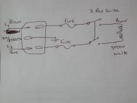
This is how it needs to be wired:
Note: The fuse can be either before or after the switch. For IEC compliance, the fuse comes first and the switch is 2 pole (switches both the black and green.white leads). If you have a single pole switch, that works but a two-pole is safer.
The second image is the IEC compliant way that the safety agencies like to see, it's safer than the first image, but your power entry module isn't set up for this as far as I can tell.
Attachments

The drawing are well understand but in practice I didnt see left and right pins in the back of the jack as in the drawing. ALthough that, there is symbols of E/N/L and I found that I switched between the N/L. I will test it tomorrow, hopefully with slo-blo fuses and see what happened. If not , I may buy a new jack locally.
The drawing are well understand but in practice I didnt see left and right pins in the back of the jack as in the drawing. ALthough that, there is symbols of E/N/L and I found that I switched between the N/L. I will test it tomorrow, hopefully with slo-blo fuses and see what happened. If not , I may buy a new jack locally.
Sounds good. Were you able to confirm that you had either L or N connected to earth? That would certainly pop all of your fuses with a dead short of mains voltage. The good news is that your amp would not be damaged, and perhaps everything else will be good!
If your module has a single fuse than one of the mains (L) would enter the module and exit through the fuse. The N connection would pass through without being fused.
With the power entry module that you have, can you wire like the first sketch above?
......or is it already wired that way?
......or is it already wired that way?
Mmmmm unfortunately no. The ground was OK. the L and N mixed up
The transformer doesn't care which end is L or N............
So I went to the shop to buy new fuses (1.25A 250V slow-blo). Changed the wiring where the L goes to the EDCOR's black wire and the N goes to the green/white wires.
SW1 was shorted, no rectifier tube. 6.3V wiring is not connected.
Still the fuse was blown and nothing happen with the transformer. Is there an option to disconnect every wire connected to the transformer and just power it up to see whether it works?
SW1 was shorted, no rectifier tube. 6.3V wiring is not connected.
Still the fuse was blown and nothing happen with the transformer. Is there an option to disconnect every wire connected to the transformer and just power it up to see whether it works?
Methodically........
Yes, good idea. First, remove all of the transformer secondary wires from the board and tape them off for safety, or VERY CAREFULLY measure the AC secondary voltages of your transformer with nothing connected to the board with the transformer powered up. Clip leads for your meter make this exercise safe.
Re-read post 33. You should have removed the jumper from SW1-SW1. The idea at this point is to change one thing at a time so you are not chasing your tail. With SW1 jumpered, you are connecting B+ to the board, and you could have issues in the B+ circuit.
If the transformer powers up and gives the correct voltages, connect the filament wires (yellow on your transformer) to the board and power up.
If the fuse stays alive, connect the brown 5V transformer leads to the board and power up again.
If the fuse is still happy at this point, connect the red & black/red HT wires to the board and install the tube rectifier without jumpering SW1-SW1 and power up.
The light bulb trick will help you a lot right now.
Is there an option to disconnect every wire connected to the transformer and just power it up to see whether it works?
Yes, good idea. First, remove all of the transformer secondary wires from the board and tape them off for safety, or VERY CAREFULLY measure the AC secondary voltages of your transformer with nothing connected to the board with the transformer powered up. Clip leads for your meter make this exercise safe.
Re-read post 33. You should have removed the jumper from SW1-SW1. The idea at this point is to change one thing at a time so you are not chasing your tail. With SW1 jumpered, you are connecting B+ to the board, and you could have issues in the B+ circuit.
If the transformer powers up and gives the correct voltages, connect the filament wires (yellow on your transformer) to the board and power up.
If the fuse stays alive, connect the brown 5V transformer leads to the board and power up again.
If the fuse is still happy at this point, connect the red & black/red HT wires to the board and install the tube rectifier without jumpering SW1-SW1 and power up.
The light bulb trick will help you a lot right now.
No success. I removed the On/Off switch and disconnect all the secondaries . Just the Black (input voltage) to L and green/white to N. The fuse was blown
Does the wires I added plays a role here? I am using copper single line 16AWG for that?!
Does the wires I added plays a role here? I am using copper single line 16AWG for that?!
The wire you have sounds fine....
So if you connect the two wires from the house mains to the transformer primary (with a fuse in one side) and plug it in, it blows the 1.25A slo blo fuse with nothing connected to the transformer secondaries?
So, mains L and N to black and green/white conductors?
Sounds like you have a transformer problem.
The transformer has 4 primary wires, correct? black, black/white, green, green/white?
Do you have the black/white and green connected together and not connected to anything else?
Last edited:

Hi.
I read in another post that EDCOR's wiring colors weren't practically as drawn in the schematics. How should I check the primaries for that?
I read in another post that EDCOR's wiring colors weren't practically as drawn in the schematics. How should I check the primaries for that?
It would be very unusual that your shiny new transformer is dead....
Sagi: Please answer the other quesstions in post 54.........
Take your ohm meter and figure out what pairs of wires go with each primary winding, then connect them in series as shown above. When you get them connected in series, the resistance across the two remaining wires will be double that of each winding. The trick is that the resistance values are pretty low, and can be tricky to measure.
Hi.
I read in another post that EDCOR's wiring colors weren't practically as drawn in the schematics. How should I check the primaries for that?
Sagi: Please answer the other quesstions in post 54.........
Take your ohm meter and figure out what pairs of wires go with each primary winding, then connect them in series as shown above. When you get them connected in series, the resistance across the two remaining wires will be double that of each winding. The trick is that the resistance values are pretty low, and can be tricky to measure.
I made small test with multimeter
Primary:
Green/white green - NONE
Green/white black - 3.6Ohm
Black/white green - 3.6Ohm
Black/white black - NONE
Sec:
Red-Red - 150Ohm
Brown-Brown - 1.6Ohm
Yellow-Yellow - 1.6Ohm
I dont know about the secondaries but they might mistake with the primary colors ?!
Primary:
Green/white green - NONE
Green/white black - 3.6Ohm
Black/white green - 3.6Ohm
Black/white black - NONE
Sec:
Red-Red - 150Ohm
Brown-Brown - 1.6Ohm
Yellow-Yellow - 1.6Ohm
I dont know about the secondaries but they might mistake with the primary colors ?!
- Status
- Not open for further replies.
- Home
- More Vendors...
- Tubelab
- Basic questions on configuring Tube AMP