Are you trying to check the value of R4 with a meter in-circuit? That usually doesn't work, as the current can be flowing all over the place. You need to have at least one end of the resistor disconnected.
Do you mean unsolder the 9pin socket pins ?
Well, interesting thing here. I checked R4 and find out it is 80K (instead of 150K) it is strange as I checked the package it arrived for model and number (but didnt the actual resistance).It may be the problem?
I usually double check resistors with a multimeter before installing them,
especially when there's only the color bands on them.
I usually double check resistors with a multimeter before installing them,
especially when there's only the color bands on them.
me too.......it's a good idea.
Well I supposed if I buy from a known firm, I should not encounter such problems.
Tomorrow I will unsolder the resistors and the pins and check what you suggested
Thanks.
Tomorrow I will unsolder the resistors and the pins and check what you suggested
Thanks.
Sagi: Your resistor values are probably correct. Measuring them in-circuit with a meter is a fruitless exercise. At least one end needs to be disconnected to measure with a meter.
R4 and R3 make up a resistive divider to elevate the heater voltage. If your B+ is say 400V, with R4 a 150K and R3 a 10K, the filament winding is elevated to 25V by being tied to the node between the R's (ohm's law voltage divider). The heaters/filaments still see 6.3V, it's just elevated from ground by around 25V. This reduces the potential between the cathodes and the heaters and means less hum/noise out to your speakers, and it is a little easier on the filaments in the tubes.
Please also let us know what you are using for a fuse, to eliminate other possibilities.
The fuse I used is 3.15A/250V . It was something I found in my house. It was written as T3.15A/250V so I dont know if its slow-bow or fast
The fuse I used is 3.15A/250V . It was something I found in my house. It was written as T3.15A/250V so I dont know if its slow-bow or fast
IIRC, the recommended fuse is a slow blow 1A-1.5A or so.
That's a little big.......don't go any larger or you'll risk damaging components.
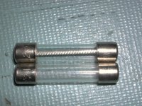
If it's a fast blow, it will just have a metal filament. Slow blows have the filament wire wrapped around some kind of insulator.
The fuse on the top is a slow blow; the one on the bottom is a fast blow.
Do you still blow fuses if you unsolder the transformer filament leads?
Attachments
Sagi: What is your mains voltage? I have no idea what country you are in.....
If it's 240V, then a 3A fuse is too big.........it's marginal at 120V.
If it's 240V, then a 3A fuse is too big.........it's marginal at 120V.
What I have now are fast bo fuses. I am using 240V so I will buy lower amp fuses.
Anyway, should I wait to unpin the transformer-heater pins or is it possible to check it with the current fuses I have ?
Anyway, should I wait to unpin the transformer-heater pins or is it possible to check it with the current fuses I have ?
Well, the safe thing to do is buy smaller slo-blo fuses...
If you unsolder/unscrew the green filament transformer leads from the board and leave out the rectifier, you can test with a fuse that you have, although a smaller amp fuse is desirable. You'll basically be testing your power transformer by itself. Convince yourself of this by looking at the schematic.
If the fuse doesn't blow, then you can suspect something in the heater circuit (simple enough...). That would be forward progress. You already know that the fuse blows with the rectifier tube out, and your FREDs aren't connected, so all that is still connected is the heater circuit. Convince yourself of this by looking at the schematic.
If it blows, you won't know if it's because of transformer inrush current blowing the fast-blow fuse, or if you have something else going on.
Can you steal a smaller fuse out of something else around the house when the wife is not looking? 😉
When you disconnect the heater wires, tape them off so they do not short on anything.
What I have now are fast bo fuses. I am using 240V so I will buy lower amp fuses.
Anyway, should I wait to unpin the transformer-heater pins or is it possible to check it with the current fuses I have ?
If you unsolder/unscrew the green filament transformer leads from the board and leave out the rectifier, you can test with a fuse that you have, although a smaller amp fuse is desirable. You'll basically be testing your power transformer by itself. Convince yourself of this by looking at the schematic.
If the fuse doesn't blow, then you can suspect something in the heater circuit (simple enough...). That would be forward progress. You already know that the fuse blows with the rectifier tube out, and your FREDs aren't connected, so all that is still connected is the heater circuit. Convince yourself of this by looking at the schematic.
If it blows, you won't know if it's because of transformer inrush current blowing the fast-blow fuse, or if you have something else going on.
Can you steal a smaller fuse out of something else around the house when the wife is not looking? 😉
When you disconnect the heater wires, tape them off so they do not short on anything.
So I made this test ( unsolder T1-grn ) with no rectifier tube and Sw1-SW1connected by jumper using fast blo 1.25amp . The fuse was blown.
Remove the jumper on SW1 and try it again. At some point, you should not be blowing fuses with everything disconnected.
If the fuse blows without the transformer secondaries connected to anything, you'll need some slow blow fuses to continue, like 1 amp rated slow blows.
If the fuse blows without the transformer secondaries connected to anything, you'll need some slow blow fuses to continue, like 1 amp rated slow blows.
Last edited:
Doesn't work again. Same phenomena.
Does the transformers should make any noise when they work? because I dont hear anything
Does the transformers should make any noise when they work? because I dont hear anything
Buy extra fuses.......
Yes, it should buzz a tiny bit when connected to the board. They usually buzz alot when they are shorted, followed by a thick acrid smoke that stinks if left connected long enough. 😉
You need to double-check your wiring to the primary side of the transformer. Are you using the Edcor XPWR131-240? If you are, you should have your mains wiring going through a power switch and fuse on the hot side, then connected to one of the transformer's black wires, and the other mains lead connected directly to the other black wire of the transformer primary.
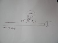
Are you familiar with the light bulb trick for getting an amp running? You take an old power cord, and wire plain old incandescent light bulb in series with one conductor of the cord, and use this cord to get the amp running. If your amp is working normally, the bulb will be very dim since the amp won't be pulling excessive current. If the amp has a short (as yours presently does) it will glow brightly. This does several good things; it's drops voltage during a short condition to help save things downstream like fuses and amp parts, and allows you to see instantly that you have a problem (if the bulb glows bright) and yank the plug.
At this point, I would disconnect all of the transformer secondary wires going to the board, tape them off and power up the transformer. If the fuse blows then, you either have a wiring problem going into the transformer on the mains side or a problem with the transformer.
That fact that you mentioned that the transformer is silent and you are blowing fuses makes me suspicious of your wiring from the house mains to the transformer.
Doesn't work again. Same phenomena.
Does the transformers should make any noise when they work? because I dont hear anything
Yes, it should buzz a tiny bit when connected to the board. They usually buzz alot when they are shorted, followed by a thick acrid smoke that stinks if left connected long enough. 😉
You need to double-check your wiring to the primary side of the transformer. Are you using the Edcor XPWR131-240? If you are, you should have your mains wiring going through a power switch and fuse on the hot side, then connected to one of the transformer's black wires, and the other mains lead connected directly to the other black wire of the transformer primary.
Are you familiar with the light bulb trick for getting an amp running? You take an old power cord, and wire plain old incandescent light bulb in series with one conductor of the cord, and use this cord to get the amp running. If your amp is working normally, the bulb will be very dim since the amp won't be pulling excessive current. If the amp has a short (as yours presently does) it will glow brightly. This does several good things; it's drops voltage during a short condition to help save things downstream like fuses and amp parts, and allows you to see instantly that you have a problem (if the bulb glows bright) and yank the plug.
At this point, I would disconnect all of the transformer secondary wires going to the board, tape them off and power up the transformer. If the fuse blows then, you either have a wiring problem going into the transformer on the mains side or a problem with the transformer.
That fact that you mentioned that the transformer is silent and you are blowing fuses makes me suspicious of your wiring from the house mains to the transformer.
Well this is interesting and I am a bit confused. The Edcor wiring says "
Black - input voltage
Green/White - common
I am using 3 pin connector (as in the computers)
There are 3 connectors in the back of the jack. One is ground and two of them are somehow connected together (short) and are on the same side (one is in the back of the fuse and one is in the back of the left pin). Nothing is on the right side of the pins.

What goes where ?
Black - input voltage
Green/White - common
I am using 3 pin connector (as in the computers)
There are 3 connectors in the back of the jack. One is ground and two of them are somehow connected together (short) and are on the same side (one is in the back of the fuse and one is in the back of the left pin). Nothing is on the right side of the pins.
What goes where ?
Well this is interesting and I am a bit confused. The Edcor wiring says "
Black - input voltage
Green/White - common
I am using 3 pin connector (as in the computers)
There are 3 connectors in the back of the jack. One is ground and two of them are somehow connected together (short) and are on the same side (one is in the back of the fuse and one is in the back of the left pin). Nothing is on the right side of the pins.
What goes where ?
Your pictures are a little small......can you post a close up that's a little larger?
What colors are the primary wires from the Edcor? What model Edcor are you using? If you look closely at your power entry module, you may see L (line), N (neutral), E (earth) near the terminals, or L1, L2, E.
Sounds like you may have a short at the power entry module. WITH THE AMP UNPLUGGED, take your ohm meter and check if your two hot leads are shorted together at the module. Since you are in 240V land, you should have 2 hots and one earth, and the corresponding terminals on the power entry module.
If you are using an int'l std power cord, your brown and blue leads are hot, and the green (or green/yellow) is earth ground.


- Status
- Not open for further replies.
- Home
- More Vendors...
- Tubelab
- Basic questions on configuring Tube AMP