R4 needs to be 15K for the linear volume control to work. It makes it act like a log pot
ESP - A Better Volume Control
Either way, shouldn't a compensation resistor be in series with signal to pin 3, not going to ground?
Adding 1K from pins 1 to 2 didn't make a difference.
Should that BW limiting cap go from pin 3 to ground?
ESP - A Better Volume Control
Either way, shouldn't a compensation resistor be in series with signal to pin 3, not going to ground?
Adding 1K from pins 1 to 2 didn't make a difference.
Should that BW limiting cap go from pin 3 to ground?
Last edited:
Stormrider... just some more thoughts on it all,
You have found for yourself that the DC offset is a real issue with the 5532 as predicted. Another important point I overlooked... that same offset voltage and bias input current will make the volume control noisy in operation.
With no output caps, R7 is not required.
The noise added by the resistors is absolutely negligable in a circuit like this.
When you measure DC offsets make sure the input to the preamp is shorted to ground. If it's floating and picking up noise etc then that may give the impression of a DC shift as the volume is turned.
The balanced line driver stage doesn't cancel DC offset and will actually add it's own offset contribution to the final output. Again using FET opamps this is negligable.
Last edited:
Tried dropping it to 10K, no change in offset voltage.
Tried this, and even though it makes perfect sense, no change.
If I drop R2, the 100K, down to 22K the dc offset on pin 1 drops to ~5mVdc but that will make my input impedance way too low.
What are you using it with that 22K is way too low? Tube gear maybe, solid state unlikely.
G²
Adding a resistor that's equal in value to R2 from the output to inverting input (instead of direct link) will minimize offset but thats not ideal from a noise pickup point of view.
The input bias current of - and + inputs have to be the same for minimum offset with bipolar devices.
The answer is to use FET opamps or if you are intent on bipolar, use single devices and use the offset null facility.
Actually my preferred option would be to use the opamps in a virtual earth configuration to minimise common mode effects. Signal polarity would be maintained.
Last edited:
if you feel you need a little gain then put that stage first instead of the unity gain buffer.
If you insist on DC coupling then learn how to eliminate the offsets of every stage. Don't let them ripple through.
If you do go with DC coupling then add a DC servo to correct the little bit of offset that is left and will vary with temperature. Finally for a DC coupling pre-amp you must include an output mute that is triggered by an output offset detector. You don't want an output offset that gets multiplied and passed to your speaker, because the source or the preamp goes faulty and the servo is incapable of servoing out a big offset.
An alternative is to AC couple the whole preamp. Good polypropylene capacitors of affordable sizes can be used without affecting the audio band if you select resistances/impedances appropriately.
The input buffer is best located at the source equipment, not at the input of the preamp. If the sources cannot drive the cables then sort the sources. A buffer at the front of the pre-amp does not sort the sources.
Thanks for the help everyone. I am going to breadboard a DC servo and test it out, but this is a new(er) schematic:
I calculated C2 using the formula C=1/(2*pi*6800*200Khz)
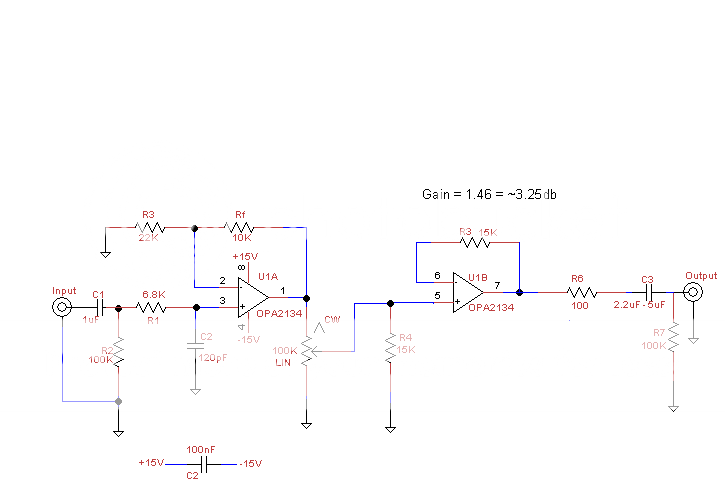
I calculated C2 using the formula C=1/(2*pi*6800*200Khz)
🙂 Everyone will have their own ideas on this.
You are not understanding the offset issue and how it works. R3 isn't needed for a FET device... with a bipolar opamp you can't equalise the input bias currents as long as the pot wiper is DC coupled.
Short out R3 and the design is OK using OPA2134 etc. Some may argue that C1/R2 is a little limiting for extreme LF performance and increasing R2 to 220k may be better.
I'm surprised the original uses a 100k pot. Stray capacitance/input capacitance of U1B means the HF response varies slightly with volume setting. I would use 10k here and alter R4 accordingly.
It's fine... any DC offset with an OPA2134 will be way to small to cause any issues.
Servos have their place, but I don't think it's here really. They add extra complications and add another "pole" into the LF response.
🙂 Everyone will have their own ideas on this.
You are not understanding the offset issue and how it works. R3 isn't needed for a FET device... with a bipolar opamp you can't equalise the input bias currents as long as the pot wiper is DC coupled.
Short out R3 and the design is OK using OPA2134 etc. Some may argue that C1/R2 is a little limiting for extreme LF performance and increasing R2 to 220k may be better.
I'm surprised the original uses a 100k pot. Stray capacitance/input capacitance of U1B means the HF response varies slightly with volume setting. I would use 10k here and alter R4 accordingly.
It's fine... any DC offset with an OPA2134 will be way to small to cause any issues.
Servos have their place, but I don't think it's here really. They add extra complications and add another "pole" into the LF response.
I calculated a 1.6hz Fc for the C1/R2 combo. F=1/(2*pi*RC)
That extra 15K is a mistake; not sure why I put it in there.
Last edited:
Ok, how's this look?
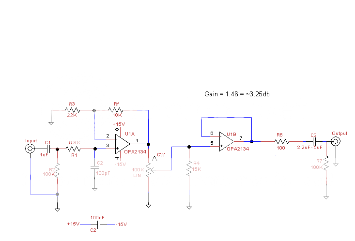
Dropping the value of the pot to 10K would make R4 a 1.5K resistor to keep the ratio the same. Is that too much of a load for the first stage?
Dropping the value of the pot to 10K would make R4 a 1.5K resistor to keep the ratio the same. Is that too much of a load for the first stage?
Last edited:
The OPA2134 is rated OK for driving 600ohm loads (to within a couple of volts of the supplies) so no problems there at all.
The input RC... well some will argue for lower 😉
It's not just the reduction in output but the phase shift that's introduced too... but again it's fine. With a cap at the output the same applies depending of course on the load the final stage works into. Some power amps may be quite low input impedance.
If you are thinking of feeding a power amp directly from this then some reliable relay delay on the speaker output may be worthwhile... the switch on thump could be pretty large 🙂
You could also always add a normally closed relay across the output of the preamp that opens after a couple of seconds... that's easy to arrange.
Input bias current compensation: The resistance "seen" by the inverting input to AC ground (supply, low output impedance, etc) needs to be the same as that "seen" by the non-inverting input to AC ground.
The assumption is that an equal amount of current flows out the inverting and non-inverting pins. If these currents develop the same voltage on the respective inputs, the differential voltage (which is what the op-amp is amplifying) is zero, hence the effects of the input bias current is compensated for.
Of course, adding resistors will cause an increase in thermal noise (aka Johnson noise). But unless the resistors are rather large (>50-100k, say), it rarely has any measurable effect on the output noise. But to figure out if it would matter in your case, you'd have to do a noise analysis. Looking at your circuit, I bet the 100k pot will be the dominant noise contributor.
As others have said already, MOSFET/CMOS input op-amps don't have any input bias current. All you're seeing with those types of inputs is the leakage current in the ESD structures on the IC and the gate leakage of the CMOS. Typically, a CMOS input will have input leakage current on the order of 100's of fA to 10's of pA (over temperature), whereas, the bias current for a bipolar is often in the 1's to 10's of nA (over temp). However, CMOS tends to be higher input capacitance, slower, higher noise (especially 1/f or flicker noise). Tradeoffs, tradeoffs...
I'm not sure why you're so worried about offset voltage. The offset voltage of the LME49720 is less than 1 mV. You hardly have any gain in the circuit, so I'd be surprised if the resulting offset voltage will exceed a few mV. I have no offset cancellation in my preamp and I have no appreciable offset on the output.
My recommended reference for op-amp stuff is: Sergio Franco, "Design with Operational Amplifiers and Analog Integrated Circuits". It's worth every penny.
~Tom
What do you mean by this?[Servos] add another "pole" into the LF response.
What do you mean by this?
That's a good question, and it depends on the exact implementation of both the circuit and the servo.
So just to wander of the original thread for a moment, I used a servo in my power amp design, and you find if you examine the LF response of the amp that the servo has an influence causing a sudden peak in the response (and phase shift) at extreme LF
It's easy to "visualise" as you can see the effect of the integrator (the TL071) reduces at LF, and starts "adding" signal back into the amplifier.
So in some ways a servo is just as bad as using coupling caps... and in a preamp I wouldn't entertain it. Here it was the only way to enable use of a single ended input stage with DC coupling at the outputs.
Attachments
Chapter 16 here might help explain it better, look right near the end 🙂
Audio Power Amplifier Design Handbook - Google Books
Audio Power Amplifier Design Handbook - Google Books
My understanding of this subject consists entirely of this Youtube video by AD. Supposing the information in that video is correct, the voltage noise of a resistor is in proportion to the square root of the resistor value. So while the 100k pot probably is the largest contributor, the other resistors at opamp inputs are not insignificant (provided that the noise overall isn't, which it very well could be considering the low gain).Of course, adding resistors will cause an increase in thermal noise (aka Johnson noise). But unless the resistors are rather large (>50-100k, say), it rarely has any measurable effect on the output noise. But to figure out if it would matter in your case, you'd have to do a noise analysis. Looking at your circuit, I bet the 100k pot will be the dominant noise contributor.
Thanks for the information. Unfortunately the last page of Chapter 16 is missing and the other pages say nothing about the kind of problem you mention. My little preamp with a servo doesn't do what you describe in simulations either (too bad I don't know how I could measure it and just that page was missing 🙁 ). I have a non-inverting integrator (not unlike Figure 16.4 of the book you linked). If I understand what you are going after, you suspect that a servo might cause the amp to oscillate or ring at very low frequencies?... a sudden peak in the response (and phase shift) at extreme LF
You ask how to measure and test this. A couple of ways you can get a feel for what happens in any given design.
Use a function generator that produces square waves down to <1hz and scope the output of the preamp as you reduce frequency. Start at say 100hz and go down. Without the servo a true DC coupled amp will produce perfect squarewaves at LF.
You can also decrease the caps in the integrator by a factor of 10 or a 100 and test at higher frequencies to observe the effect of the integrator... using both sine and square.
Every implementation and circuit configuration will be different will be different...
Servo questions have cropped up from time to time on here,
http://www.diyaudio.com/forums/chip-amps/130077-another-dc-servo-question.html
http://www.diyaudio.com/forums/solid-state/3754-dc-servo-output-drift.html
Naturally it's better to have neither a DC servo nor caps as a general principle, but is there something inherently 'evil' about DC servos that I'm missing here? (Lot's of people seem to be upgrading their equipment with servos, to do away with caps.) As discussed, in designs like Stormriders (and mine), the amp offset can readily be eliminated by using low Ib, low Vos opamps. Would you say that it's always preferable to use such opamps and do away with the servo or caps, even if something like NE5532 would be deemed better (for what ever reason people might prefer a certain opamp with similar performance over others), or is it a matter of personal taste? I think I might by an OPA2134 and do some listening...Without the servo a true DC coupled amp will produce perfect squarewaves at LF.
I would say there is nothing wrong with servos at all if properly implemented.
Having said that, for a line level stage, I would look at ways of getting similar results without using one. Why ? because in a power amp we know that a speaker is never going to be asked to be presented with a squarewave at 1 hz with flat tops and bottoms. Hmmm a preamp... why compromise at all when you can design without that complication by using FET opamps where needed etc.
If you are really intent on using say a 5532 then you have to consider is it best to use AC coupling (such as in the VC wiper on Stormriders circuit) perhaps using a 0.47 film cap and 470 k bias resistor, or go down the DC coupled route and use a servo. I would probably go down the AC coupled route on that one.
Thats another route I could go; adding a cap after the vol control. You say a .47uf after the pot and R4 (that 15K), and a 470K resistor to ground after the cap? Isn't that kind of a big value?
- Status
- Not open for further replies.
- Home
- Amplifiers
- Chip Amps
- Basic opamp based preamp