Thanks for the clarification Hugh! I nearly asked that exact question (ie do you need more output pairs to do that?) when I saw your post. My initial reaction was wow that means there is potential for a lot more than 50W (not that I need it these days anyway) 😉
Tony.
Tony.
This topology is scalable into a pro-amp level. In my country this pro-amp module is recognized as the "Open Air". Good for vocal.
The amp can be run with 62V rails with more output pairs, three in fact. Up to 42V with a single pair, 50V with two, and 62V with three pairs.
Very interesting, you may have just solved a problem for me. Thanks. 🙂
'Alam terbuka' Jay?
Hugh
Yes 🙂 May be because the openness/forwardness of the sound
Al,
Nice build out! Some suggestions:
#1 Reduce R15 inter-emitter driver resistor to 100R.
#2 Incorporate 10R base stoppers on all three output device pairs, one for each device.
#3 Reduce driver base stoppers R13/R14 to 47R.
#4 Reduce R10 to 47R.
#5 Replace Q3 with a 150V transistor; 2SC3423, or 2SC3600 (Sanyo).
#6 Reduce C5 to 47R.
#7 Insert a silver mica 12pF from collector of Q3 to base of Q2.
#8 Reduce R4 to 1K5.
#9 Replace R3 with 43K resistor and 10K trimpot in series, to enable offset adjustment.
#10 Increase C100 to 470nF, polypropylene.
#11 Use 220uF for C10 and C12 rail decouplers.
#12 Decrease R21 and R22 to 33R to keep dissipation down without a fuse.
#13 C3 should be 100uF.
Quiescent should be 60mA through each output pair. With 62V rails this gives around 25W standing dissipation including drivers at idle, so you'd better have a good heatsink, something no less than 0.2C/W. The amp should do around 200W, clipping at 56.5Vpeak, depending of course on the power supply.
Hope this is helpful,
Hugh
#14= increase R5 and R6 to keep VAS current the same. I would guess 3.9k/5.6k for 6.5mA @60v rails. I started with 2.7/3.3k at 40V = 6.7mA on my test PS , when I ran the amp with 70V rails I had 12+ ma+... changing the Vbe and underbiasing the OPS into class B. This is unavoidable with a non- current sourced VAS. The "blameless" will hold 6.2mA from 80V to under 10V rails.
OS
OS
Hi Hugh, and thanks for sharing this circuit with us, (and Greg as well! )I'll get back on this in a day or so to update the schematic with your suggestions, but I've got to clean and service a Soundcraft 8000 mixing desk first - work before pleasure!
First thoughts on some of your points, I'll have to get my brain in gear to consider the others, and it's bedtime now:
2#Yup, agree completely, but occurred to me after I'd posted the schematic.
5# I was considering the MJE340 as the VAS, for the same reasons, faster and higher voltage. How does it compare to the Sanyo parts?
7# Ah, the mysterious phase lead cap? 😉
9# Again, crossed my mind after I'd posted
10# That value was purely a guesstimate, based on other amps of similar size. Despite scouring Self and Sloane, couldn't find a way of calculating it. Is there a formal method, or is it just experience?
11# I was split about this, the need for more decoupling evident, but I wasn't sure if it would be better to split it and add another 100u+100n between the output stage and the input stage.
12# Doh, should have spotted that!
13# Even bigger doh, can't even type correctly! 🙂
Ta OS, something else to consider. I can see I'll be drinking lots of tea on Friday whilst I get on top of all this. 🙂
Hello
For the #6 Hugh suggestion, he was mean to reduce C5 to 47p (not 47 R) but i think all guy would have see that.
BD139 are slow and do have a high Cob for a VAS, so a faster one are good, I like to use the KSC3503 or 2SC3503 for the VAS of my diy amps.
Yes, Hugh's suggestions of reducing C5 and adding a phase lead cap are a nice gift and it will light-up the Baksa.
Bye
Gaetan
Last edited:
Sony TA-1055
I haven't seen people discussing the circuit similar to the one used by Sony TA-1055. It uses similar topology with the B/AKSA except that it is quasi complementary! But wait, I think the LTP is using NPN like P3A. I don't know with you but to me being able to build an amp with only N-channel transistor is a big benefit. Old UPS, old power supply, can provide you with the transistors.
Just like the B/AKSA variations, TA-1055 is also sweet sounding (even better than TA-1066 which is complementary), quite different than a lower power Quasi NBIP.
Now, that I see a high power version of BAKSA with an acceptable quality transistor to achieve 200W+, I am thinking to have the same power but in quasi-complementary setup (like the TA-1055). It would be useful and who knows it could be different sounding...
Hello pinkmouse
I've look for the MJE340 you want to use for the VAS.
The Motorola MJE340 Ft was 24MHz, other brands are not very much faster, so it's slow for a VAS.
The VAS transistor should have a FT of arround 125 mhz and a Cob lower than 10 pF.
Try to find some KSC3503 or 2SC3503 for the VAS.
Bye
Gaetan
I've look for the MJE340 you want to use for the VAS.
The Motorola MJE340 Ft was 24MHz, other brands are not very much faster, so it's slow for a VAS.
The VAS transistor should have a FT of arround 125 mhz and a Cob lower than 10 pF.
Try to find some KSC3503 or 2SC3503 for the VAS.
Bye
Gaetan
Last edited:
Gaetan,
Many thanks! From my experience you are right on the money.....
OS,
With higher voltage rails, it's a good idea to have more current flowing in the VAS to supply more drive to the drivers, which must now deal with three output pairs. We are driving a highly variable output stage with the collector of transistor, very high source impedance. More current gives less distortion. If you assume peak current at 200W//8R is just over 7A, then combined base drive will peak at around 80mA for the C5200/A1943 assuming an average beta around 90. If the driver has a beta around 80, then base drive will be over 1mA. I like to set a bridging ratio of around 10 between VAS current and peak driver current - purely a convention I have - and with R5 + R6 of 5k5 we have around 10mA of VAS current, which is right on the mark.
The VAS will naturally be heatsinked, since it's dissipating around 560mW, but with a TO220, even at 6.5mA, this device should still be heatsinked, so it's no big deal.
That said, YMMV, and likely will. This is opinion, not fact, and I merely present my approach, based entirely on my experience, which is considerable with this topology. The devil is of course in the detail.....
Al,
There is no effective way to dimension the charge suckout cap. For each pair it typically should be around 150nF, so three pairs, with three pairs of bases to serve, would proportionately be roughly 470nF. The quality of this cap is important however, a low DA is required. You can tune the best performance by varying the parallel resistor. Three pairs would be around 100R, but anywhere from 68R to 120R would be best arrived at empirically.
Al, the Toshiba 2SC3423 is an ideal transisor for this role, rated to 150V, 200MHz, with Cob of just 1.8pF. It is rated for beta from 80-240 at 10mA, with max Ic of 50mA. This is highly suited to this application. The Sanyo 2SC3600 is probably better again, but almost unobtainium, even in Asia.
Cheers,
Hugh
I'm tempted to add a little more supply decoupling after the power stage. Any comments?
Hi pinkmouse,
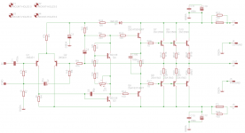
I was doing a bit of research last week and came across post #340 posted by Hugh a few years ago. I forgot that Hugh had posted this schematic and it has a few extra components on it that I missed on my PCB. Maybe you should make provision for them on your PCB.
http://www.diyaudio.com/forums/ever...t-us-see-schematics-forum-34.html#post1652112
I would also include 2 diodes across the earth lift resistor R2.
regards
I forgot that Hugh had posted this schematic and it has a few extra components on it that I missed on my PCB.
You missed it?? I thought you didn't want to show the details. Remember that on the post #340 you cannot see the value for some components.
Like I said in my earlier post in this thread, I doubt that you can achieve a quality close to AKSA with your simple feedback scheme. My AKSA clone uses all the components displayed in post #340 plus 2 more components. Yes, I use Vbe multiplier while in original AKSA I guess diode string is used instead of transistor.
Jay,
You have done a very good job of copying the original AKSA, it seems, so you can see why I moved on..... very hard to keep these good designs secret!
My more recent work is much better than the AKSA, and I do not ever share the details in public forums... but even so, I can assure you there is more in your AKSA yet.
Sayang tak bisa bercakap-cakap di restoran di Blok M tentang hal-2 audio......
Hugh
but even so, I can assure you there is more in your AKSA yet.
No doubt. I guess I know what is missing with my AKSA clone or with bipolar amps in general. One easy way to improve I believe is to use appropriate output transistor. I have faith in the big package Sanken 2SC2922 but I have shopped around and found none that I think is original.
I know that it is impossible to get comparable quality from a higher power version, but 200W, wow, I really like to start with Pinkmouse's circuit and the suggestions you wrote to update that circuit.
My more recent work is much better than the AKSA
Sure I believe so. If it is not, then you're in the wrong track 😀 But if your design is based on mosfet (which is not), I will jump to pool full of shark to get the copy 😀
Indeed, it is theoretically impossible to hide secrets in this kind of business. What is more important is your quality to be able to come up with good designs. But guess what, I don't really care with the quality of amps. I know that the real secret lies in speaker design.
Speaker design is also easy to be copied, even if you custom order the drivers (which require you to order around a thousand minimum I guess). But if you design the amp complete with the active crossover and the speaker, once you achieve what is possible, no one can copy, and many will happily throw their dollars to get something that is possible to create, without ever questioning the price tag.
Audio fanatics are everywhere but I still found that no consensus have been made between "designers" on what should be achieved within a design.
2SC3600 Ouch!
2SC3423 A bit more reasonable, but no idea if it's Toshiba
2SC3503 At last, a branded part Good price as well.
2SC3423 A bit more reasonable, but no idea if it's Toshiba
2SC3503 At last, a branded part Good price as well.
Al,
I see Donberg has the 3600! It's the price of a stiff drink, but the pleasure would go on for years..... why not give it a try?
The specs on that transistor have to be seen to be believed; 200V, 1.4pF, 100mA, 400MHz, man, that's some technology.
Hugh
I see Donberg has the 3600! It's the price of a stiff drink, but the pleasure would go on for years..... why not give it a try?
The specs on that transistor have to be seen to be believed; 200V, 1.4pF, 100mA, 400MHz, man, that's some technology.
Hugh
Last edited:
- Home
- Amplifiers
- Solid State
- Based on Hugh Dean's AKSA 55