I am obliged to correct my senseless error in the above post re: output inductors. One should not shoot from the hip without accuracy. The inductor, damped by R to limit ringing with cap. loads, is indeed to prevent load induced instability. Apologies all.
Hi Rabbitz, you might want to try parts connexion.
Tony.
Hi Tony
I haven't had much luck with them in the past as the ordering system was long winded for international orders. I tend to use Michael Percy but can be hard to get his attention. I found it best to place a Paypal order x shipping which he responds to quickly.
HiFi Collective in the UK has them as well and even though more expensive are a reliable source.
HiFiCollective
my thoughts on the Zobel (part solution) and the Thiele Network (almost the full solution) is that the filter that is fitted between the amplifier and the speaker terminals has a lot of different functions.
The Zobel part (R+C) is an HF load to help keep the amplifier stable when no load is attached.
The L//R is to help prevent cable effects from applying an excessive capacitive load on the amplifier reducing it's gain and phase margins and in worst case becoming unstable.
The R+C across the speaker terminals is there to attenuate RF coming back down the speaker cables and getting into the amplifier's feedback loop where it will try to amplify that RF at it's -IN terminal.
This description of the purpose of each part shows that the optimum location is neither at the amplifier nor at the speaker terminals. The three parts need to be fitted where they can best do their own job.
The Zobel R+C should be fitted very close to the output devices and the output decoupling.
The L//R is non critical, but the effect of chassis on the inductor and the effect of inductor on the amplifier may require it to be located away from both, i.e. in the cable between amp and terminals but remote from amp and chassis.
The RF filter R+C must of necessity catch the RF at it's point of entry and must be located right on the speaker terminals, using the lowest inductance connections/lengths as possible to attenuate the highest frequencies, including the mobile cellphone.
Hi & thank you Andrew. That covers much more as you say. I am mystified by a third element you refer to as an R+C at the O/P terminals which probably only illustrates my deeper ignorance. Yes, I have seen small caps at output terminals occasionally on amps from too long ago to be relevant but certainly on a lot of commercial PA gear. Perhaps the drift to UHF, and higher frequency comms. now requires this approach for immunity?
Thiele's O/P network is still a bit of a puzzle to many engineers. It is claimed that the commercial version output end of the coil for the C position of the zobel, (which shares same R with L) is wrong. Confusing? Needs a diag. I guess but can't assist currently. There are only three components so please bear with me. I don't want to complicate this issue since I can't support it but since you raise it......
Thiele's O/P network is still a bit of a puzzle to many engineers. It is claimed that the commercial version output end of the coil for the C position of the zobel, (which shares same R with L) is wrong. Confusing? Needs a diag. I guess but can't assist currently. There are only three components so please bear with me. I don't want to complicate this issue since I can't support it but since you raise it......
Thanks Andrew,
It makes sense to me now. I was going add a second set of R-C to the PCB at one point after reading your recommendation in another thread. So, if I reverse the input and output on my PCB and mount it close to the output posts and place to zobel components on the PCB I'll have covered all bases.
regards
Hi Tony
I haven't had much luck with them in the past as the ordering system was long winded for international orders. I tend to use Michael Percy but can be hard to get his attention. I found it best to place a Paypal order x shipping which he responds to quickly.
HiFi Collective in the UK has them as well and even though more expensive are a reliable source.
HiFiCollective
I think maybe they have changed their ordering process (the site mentions something about it being long overdue). Basically I put everything in the shopping cart, checked out, they sent me an email confirming my order, they then sent another email advising that some of the parts would be on backorder, and finally another email when the goods shipped. I did have to respond that the order details were correct before they proceeded. As I mentioned I didn't find out what the shipping cost was until after they had processed and shipped the order, so there is no backing out, this is definitely a deterrent for international customers in my opinion.
I am planning on ordering some more stuff hopefully in the not too distant future, so if you (or Greg) want some KZ's let me know and I'll add them to the order, provided the quantity isn't high it shouldn't impact on my shipping costs 🙂
Tony.

do not accept my description as Gospel.
These are bits I have gleaned from the Forum and assembled into what I think makes sense.
There are certainly other views.
Search them out.
These are bits I have gleaned from the Forum and assembled into what I think makes sense.
There are certainly other views.
Search them out.
Here's a PDF of the PCB.
Greg, thanks for sharing the layout. A few (major and minor) quibbles:
1) How are the emitter ballast resistors actually fitted? The traces for these seem to go
off the edge of the PCB.
2) Space for input coupling capacitor - probably not enough for a large axial-lead device, even when mounted vertically.
3) the length and width of the resistors, especially R9, the feedback resistor. It would help if they were wider and longer, to help accommodate 2W Kiwame/KOA-Speer carbon films. There's enough space on the board, by moving around a few parts and traces, to make this possible.
4) It would help to leave outlines and unconnected pads for a few uncommitted resistors and silver micas, for those who might want to experiment with different compensation schemas, including Hugh's unpublished addenda to the basic AKSA schematic.
Hi LG,
Nice to see you here, thanks for dropping in. I owe you some boards, too, I promise I will send them soon but there is always a better circuit and I do a new one every six months!!
The input cap on any LTP amp is always crucial to sound quality. The better this cap, the better the sound, since it has no appreciable polarising voltage across it, generally less than 100mV. If you put a quality cap here, such as an Auricap, or (gasp!) a Sonicap, the size is enormous, and not very practical. Moreover, I've found large caps tend to pick up EMI from the output inductor, so as a general rule I allow for a compact cap of lesser quality on the board, bridging this cap if I use a large, high quality cap off board, well away from the output inductor.
Do you consider that the larger boutique resistors, such as the Kiwame, are worth using? I've tried them, they add just a little warmth, but by and large they are hundreds of times more expensive for limited return.
One feature that might be useful is provision for VAS degeneration. I have found very slight improvements in smoothness and refinement by using a 10R here. Otherwise, it can simply be linked.
Large pads for both lag compensation and phase lead are good ideas, since these components are pivotal to the sonics and the enthusiast may wish to chop and change here. Small differences have profound effect on sound quality.
There is nothing new technically in this design; it's a hotch potch of other people's ideas. BUT, with very careful component choice and dimensioning the sound quality is stellar, quite unexpectedly, although THD is not that low, around 0.05% at full power 1KHz. It's a tweakers dream, but not a technical tour de force. There is a hidden mechanism in the AKSA and I challenge anyone here to find it. Only two people in over ten years have twigged to it; it really is quite subtle. Rabbitz, nothing outta you, pal!!
I support this venture from Greg, since the AKSA is no longer a commercial product, I've moved on. Believe it or not, my new amps sound better still, but we are operating at the limits here and improvements are incremental. This is a VERY good basic amp to start out with, good enough for a sophisticated audiophile to appreciate,
Cheers,
Hugh
Last edited:
Member
Joined 2009
Paid Member
Only two people in over ten years have twigged to it; it really is quite subtle.
I think I had 99% of it, so make that three 😎
Call me lazy, but I've never used output inductors. I understand their use and if I were making a commercial amplifier I'd want to include one because the amp must cope with a large range of possible load conditions. At home I don't bother. Having said that, I have an L+R for baffle step correction in my DIY speaker and it sounds very nice.
Gareth,
Silly boy. You were the second........ when you sell amps, disasters are inevitable, so you plan for them. You MUST use an output inductor, because people use all sorts of different loads, some of which are very, very nasty.
Silly boy. You were the second........ when you sell amps, disasters are inevitable, so you plan for them. You MUST use an output inductor, because people use all sorts of different loads, some of which are very, very nasty.
Last edited:
Greg, thanks for sharing the layout. A few (major and minor) quibbles:
1) How are the emitter ballast resistors actually fitted? The traces for these seem to go
off the edge of the PCB.
2) Space for input coupling capacitor - probably not enough for a large axial-lead device, even when mounted vertically.
3) the length and width of the resistors, especially R9, the feedback resistor. It would help if they were wider and longer, to help accommodate 2W Kiwame/KOA-Speer carbon films. There's enough space on the board, by moving around a few parts and traces, to make this possible.
4) It would help to leave outlines and unconnected pads for a few uncommitted resistors and silver micas, for those who might want to experiment with different compensation schemas, including Hugh's unpublished addenda to the basic AKSA schematic.
Hi linuxguru,
Thanks for the feedback. I'll keep them in mind if I get some more PCBs made. I haven't planned on that at the moment. Also, I am restricted to 100 x 80 mm PCB size by my Eagle license. I can't justify the cost of a license for a non profit venture.
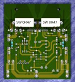
The emitter ballast resistors are just soldered under the PCB onto pads without holes. This is pretty much the way Hugh did it on the original PCB and it really helps keeping the PCBs size down.
regards
Attachments
Member
Joined 2009
Paid Member
A quick look at the pcb (it does bear a resemblance to the original !)
a) are there film decoupling caps to the supply rails ? if not, perhaps there is space in front of C10 and C12
b) Hugh didn't include a dc offset adjust pot in AKSA and I followed this with my TGM amps. But I later found it a PITA, causing me some desoldering/soldering. So I wonder if it's worth adding a pot in parallel with the LTP load resistor to allow for some easy adjustment.
c) For the feedback cap do you want to use a bipolar cap to avoid the need for protective diodes across it (which you might want if using a polarized electrolytic in that spot) ? A smaller bipolar for C2 would create all the space you want to put a pot across R3 for easy dc offset adjustment.
d) In the very unlikely event of output oscillation the zobel resistor will get warm (or even quite hot) and it can help to size R19 a little large to allow for this
For TGM I did the same with the output emitter resistors, it's a very smart choice but I did include holes in the pcb as this made soldering them in a little easier
Hi Gareth,
Thanks for your comments.
Not quite as nice as the original. 🙂
Have a look at the under-PCB picture a post or 2 back. Those squares are them.
The first 2 amps had single digit DC offset. Best I have ever got. The one using BD139/BD140 is another story.
I'm using a 22uF WIMA at the moment. It should be better than a electrolytic, but I will be testing some to see.
I do have 1 watt resistors on the external zobel. I have been measuring the temperature of all the components of this amp. The zobel/inductor network don't increase temperature at all, well they must a bit but not even a degree.
These resistors are directly under the heatsink ledge, so having holes in this case is risking a short.
regards
Thanks for your comments.
A quick look at the pcb (it does bear a resemblance to the original !)
Not quite as nice as the original. 🙂
a) are there film decoupling caps to the supply rails ? if not, perhaps there is space in front of C10 and C12
Have a look at the under-PCB picture a post or 2 back. Those squares are them.
b) Hugh didn't include a dc offset adjust pot in AKSA and I followed this with my TGM amps. But I later found it a PITA, causing me some desoldering/soldering. So I wonder if it's worth adding a pot in parallel with the LTP load resistor to allow for some easy adjustment.
The first 2 amps had single digit DC offset. Best I have ever got. The one using BD139/BD140 is another story.
c) For the feedback cap do you want to use a bipolar cap to avoid the need for protective diodes across it (which you might want if using a polarized electrolytic in that spot) ? A smaller bipolar for C2 would create all the space you want to put a pot across R3 for easy dc offset adjustment.
I'm using a 22uF WIMA at the moment. It should be better than a electrolytic, but I will be testing some to see.
d) In the very unlikely event of output oscillation the zobel resistor will get warm (or even quite hot) and it can help to size R19 a little large to allow for this
I do have 1 watt resistors on the external zobel. I have been measuring the temperature of all the components of this amp. The zobel/inductor network don't increase temperature at all, well they must a bit but not even a degree.
For TGM I did the same with the output emitter resistors, it's a very smart choice but I did include holes in the pcb as this made soldering them in a little easier
These resistors are directly under the heatsink ledge, so having holes in this case is risking a short.
regards
any particular reason for this choice of output topology?
Hi Pete,
Who is this question directed to?
If me, I am just following what the original had, to a degree.
regards
Peter,
The Self EF II is simple, and it works very well particularly when tweaked with charge suckout network. The DEF is widely used in pro-audio because it is reliable, stable, and good sounding. If we ignore single ended topologies, the only other choices are triple EF, which is very good but can be difficult to thermally stabilise and in any event best on multiple output pairs, the CFP (when stabilised very tetchy to bias and sounds ordinary) and the diamond buffer, which features a high bias regime for the drivers which is inefficient and requires two current sources, added complexity.
Answer your question? All were built and compared, BTW.
Hugh
Nice to see you here, thanks for dropping in. I owe you some boards, too, I promise I will send them soon but there is always a better circuit and I do a new one every six months!!
Hi Hugh - no problems, I've been lurking here off and on, both at chipamps and solid-state. I have been warming up to the Symasym variants (especially the Chinese M7) as a tweaker's paradise.
Moreover, I've found large caps tend to pick up EMI from the output inductor, so as a general rule I allow for a compact cap of lesser quality on the board, bridging this cap if I use a large, high quality cap off board, well away from the output inductor.
A useful insight - I too had found that a compact film like a Wima polyester 1 uF/63V or a small electrolytic like a Muse or Silmic, is perfectly adequate as an input cap, but I hadn't connected the dots to the EMI issue.
Do you consider that the larger boutique resistors, such as the Kiwame, are worth using? I've tried them, they add just a little warmth, but by and large they are hundreds of times more expensive for limited return.
Only for the feedback network, or in a pinch, only the feedback resistor. I found that metal-films can be harsh sounding at that location, probably due to their self-inductance. A carbon composition is ideal, but they're unobtainium and/or drift with age. A Kiwame or KOA-Speer 0.5W is a perfect compromise - accurate, drift-free and but still warm-sounding. The KOA-Speers are not that expensive yet for most values and wattages.
Last edited:
Hi Greg, re:'Who is this question directed to?' - anyone who cares to answer, just trying to get a handle on the reasons behind OP stage choices, & thanks Hugh for the comprehensive answer 🙂
Gareth,
Silly boy. You were the second........ when you sell amps, disasters are inevitable, so you plan for them. You MUST use an output inductor, because people use all sorts of different loads, some of which are very, very nasty.
Even when you plan for them you never cease to be amazed at what "punters" will do 😉
- Home
- Amplifiers
- Solid State
- Based on Hugh Dean's AKSA 55