More Results From Survey of 2016/2017 Results
More info, results of many tests. Easy to do after the mule is setup.🙂
More info, results of many tests. Easy to do after the mule is setup.🙂
Attachments
-
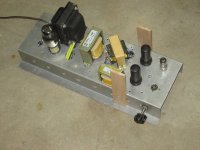 IMG_2081 Self Inverting Amplifier Mule.JPG504 KB · Views: 137
 -
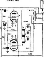
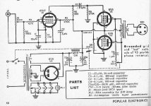
 250R to Common Self Inverting Amplifier Popular Electronics.jpg59.8 KB · Views: 128
 -
 Sparton 8549 Output Section 6H.jpg69.4 KB · Views: 112
 -
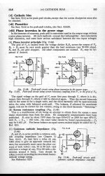 RDH4 p 585 30C Self Inverting Push Pull.jpg455.6 KB · Views: 121
 -
 2017_02_03_001.jpg47.8 KB · Views: 106
If I remember correctly, a 25 Watt incandescent light bulb is very similar to a ballast.
It has a very unstable resistance, depending on how much voltage you put across it.
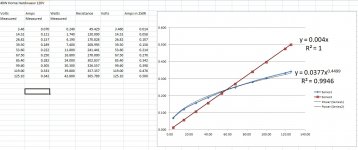
Sez who? Here is an example, a 40W tungsten incandescent bulb compared to a 250R resistor on the same scale. Resister is a straight line while a tungsten filament lamp increase resistance as the temperature rises.🙂
But stable at operating temperature. Otherwise our lamps would be randomly flickering. They don't.🙂
Attachments
jhstewart9,
I am already promised to draw and send a schematic of another one of my amplifiers to another poster on this Forum.
After I get the time to draw and send him the schematic, I may, or I may not, remember to draw and post the schematic of my self inverting push pull amplifier on this Forum.
Shew it indeed.
I love King James era language.
But I find our current language more full of puns; which I like even better.
In Post #20 you said 'But I still listen to the 6BX7 self inverting push pull amp with choke and resistor current sink'.
That sounds a lot like the various coke/resistor tail combos I tested.
Most folks could draw a schematic & post it here in minutes . What is your problem? How about a photo.🙂
Interesting, I looked up Gyrator chokes, it looks like they could work well in a power supply but not so good as a plate choke, unless your intent is to add some distortion. Any idea what this distortion would sound like? Since it would be limited to the voltage applied I assume it would not be at all like a swing choke, in fact it would be more like a saturated choke? More of a current limiter? I don't see how it could store energy like a choke.
Blaxshep,
It is rather a matter of reactance. An inductive plate load gives a harsh, hard and cold sound.
Maybe we should not go deeper into this.
A 5% 1000 Ohm 25 Watt wire-wound resistor at standard temperature, resistance will be from 950 to 1050 Ohms.
If it dissipates 0.0 watts, or if it dissipates 10 Watts, the resistance will change much much less than an an additional 5%.
I call that a stable resistance. Stable resistance within its power dissipation limits.
In my amplifiers, I generally use a 3:1 to 5:1 rule. I use a resistor that has a power rating that is 3 to 5 times the power that it will dissipating. Cool, man.
A 25 Watt incandescent lamp, as I said, is not a stable resistance. The cold resistance is one thing. The resistance when it dissipates 25 Watts is another thing.
Now try 10 Watt dissipation.
Stability has more than one meaning in my 1968 Random House Dictionary.
I am sorry that my American version of the English Language is not very clear.
If you think I murder the language, because I am not clear or accurate, then
please do not watch any TV network nightly news. You might choke.
Prevent choking.
In 1959, I listened to the optical hum signal produced by an incandescent light bulb.
I used a silicon solar cell and a headset.
Although a tungsten filament has some thermal inertia, it changes the temperature and light output enough that it sent out a 120 Hz optical hum signal.
As one of the posters in this thread already mentioned, a filament acts as a low pass filter.
Like an imperfect low pass filter, It does not have enough ultimate rejection at 120Hz;
Why 120Hz, because the filament heat is dependent on the voltage and resultant current of each Alternation, the polarity does not make a difference to the filament output.
Even the filament is not a stable resistance, or there would be no optical hum signal, no matter how small of a signal.
Resistance Stability?
Last edited:
jhstewart,
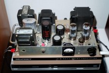
I like your test chassis.
And I like those old metal 6L6 tubes.
Perhaps I will draw up a couple of schematics soon.
I like your test chassis.
And I like those old metal 6L6 tubes.
Perhaps I will draw up a couple of schematics soon.
Tublab_com,
You are so creative.
A 20 Watt Guitar amp with those tubes, and self inverting at that.
I sometimes envy the Guitar Amp designs, and designers.
They can use SE Pentodes and Beam Power tubes;
And they can use Push Pull Pentodes and Beam Power tubes.
Those amps drive a single Guitar speaker that has been selected
for its characteristics, and the cabinet it will be used in.
Hi Fi frequency response, Hi Fi low distortion, and good damping factor are not required.
With all of that, they do not have to resort to either using negative feedback, or using those Beam Power tubes and Pentodes in Triode wired mode.
Last edited:
Very interesting!
SE output stage very similar to what I've been playing with the 6P6S, triode wired, exactly the same values for bypassed cathode, but I settled with diode bias at -25V, with B+ of 370V to keep within the 6P6S ratings (if I recall, slightly better than 6V6)
I really like your feedback network.
I didnt think to take feedback in such a way, and I am curious to try it on my own circuit!
no pentodes for input stage though.. maybe a cascode stage instead...
Got me thinking how to morph that input stage into cascode...
I ran the 6P6S in almost exactly the same conditions, in my circuit, but with added plate to grid feedback, and in tetrode mode, or triode mode, the THD was very similar, albeit at slightly different power outputs, so I expect your circuit performs well!
(I dont know how effective the feedback is on the THD, as I have never used it in that way)
Very cool
Last edited:
A 20 Watt Guitar amp with those tubes, and self inverting at that.
Actually the 2 watt P-P version was the only self split version. The others used a mosfet split load PI. The self split thing needs a CCS or large resistor to a negative supply to get the second tube doing it's share of the work. That pretty much restricts it to class A operation. A choke with suitable DCR and enough inductance works quite well, but doesn't fit in well with ultra low budget.
The 20 watt amp on a breadboard works fine (heaters, screen and B+ supply) from a $15 Triad N-68X isolation transformer. It needs no negative supply, but uses a novel new design that I dreamed up several years ago and finally got right. The output stage is good enough for HiFi if a suitable OPT is used.
See post #9 in this thread for the details:
G2 using MOSFET ultralinear feed
A SE HiFi version that makes 20 to 30 WPC already exists and is on it's way to being the next Tubelab PC board.
UNSET is coming?
The 50 - 75 WPC push pull version needs the mosfet PI from the breadboard guitar amp and it will turn into a new board. The breadboard guitar amp was really a test bed for that design. It will be a new toy when finished. Several test and refinement iterations are still needed on the P-P HiFi amp before I can put the Tubelab name on it.
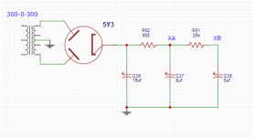
This is my only remaining self inverting push pull amplifier.
It has a 6C45pi triode driver, and two 6CK4 triode output tubes.
The constant current sink for the 6CK4 cathodes is a 200mA 5H choke, in series with a resistor to get the quiescent current I want.
The 5H choke was the best I had for that application, it was better than the 100mA 20H choke I had (the 20H saturates at bass frequencies).
The constant current choke needs to work all the way down at Bass frequencies (When used as B+ filters, chokes only have to work at 120 unidirectional alternations).
There is a 25 Ohm pot, the wiper connects to the constant current sink, the ends connect to the 6CK4 cathodes, so the plate currents can be matched in the Fisher 500 push pull output transformer. That keeps the OPT core from early saturation.
6CK4 tubes were selected to be close enough so that the 25 Ohm pot can 'finish' the DC current balance.
Sorry, the power transformer and chassis are all that remains of the original Heathkit amp.
(Nobody ever took an old 49 Ford, pulled the engine, and the rest of the running gear, and put in a V8, transmission, beefy suspension, radial tires, and differential to match) Right?
I am listening to the amp I described above, that you see in the picture.
The CD is of Rebecca Pidgeon "The Raven" Chesky JD115 on an Usher S520 2 Way Loudspeaker, 2 feet from my ear, next to my computer.
Sounds good to me.
Attachments
Last edited:
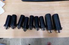
Those are metal 6V6's. The 6L6's are taller and fatter.
I blew up several dozen NOS metal 6L6's in high school electronics class, all furnished by the USAF. The teacher even bet me that I couldn't make the outside metal envelope glow red. It stunk up one whole wing of the school, but I won that bet.
I got a box full of metal tubes for free at the Dayton hamfest a few years back. These are slated for MetallicAmp, a guitar amp that is All Tube....No Glass! I'm leaning towards two independent output stages with a pair of 6V6's in each. I can get 30 watts per pair from these easily in AB2. All 8 have been tested at this level after I verified the design with some old glass RCA's where I could watch for hot stuff.
A common transplant in the 60's.....but there was always the "dare to be different" guy who put a supercharger on the old flathead.
I blew up several dozen NOS metal 6L6's in high school electronics class, all furnished by the USAF. The teacher even bet me that I couldn't make the outside metal envelope glow red. It stunk up one whole wing of the school, but I won that bet.
I got a box full of metal tubes for free at the Dayton hamfest a few years back. These are slated for MetallicAmp, a guitar amp that is All Tube....No Glass! I'm leaning towards two independent output stages with a pair of 6V6's in each. I can get 30 watts per pair from these easily in AB2. All 8 have been tested at this level after I verified the design with some old glass RCA's where I could watch for hot stuff.
(Nobody ever took an old 49 Ford, pulled the engine, and the rest of the running gear, and put in a V8, transmission, beefy suspension, radial tires, and differential to match) Right?
A common transplant in the 60's.....but there was always the "dare to be different" guy who put a supercharger on the old flathead.
Attachments
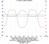
One "advantage" of a self inverting push pull amplifier is that as long as you do not drive it into clipping, it is all Class A.
Somebody says, Only Class A?
How much power does it put out in Class AB?
I tell them it puts out 2X the power in AB as in A.
The same peak voltage out, but 100% clipping, a square wave, hence 2X the power.
I have to remind them that I only listen in Class A on that amplifier.
Tubelab_com,
You got my point.
I have been criticized by some for "ruining" a "priceless" old Heathkit amplifier.
Just do not tell anybody that I have a Dyna Stereo 70 that has been a mainstay test bed for many push pull, single ended, DHT, Beam Power,
and Pentode amplifiers (Mono-Block and Stereo too).
The (ugh) Steel chassis and Power transformer are all that remains of the old ST70.
Well, I did keep the Dyna output transformers too.
I took one of them and re-stacked the laminations, E's, Air Gap, and I's. It is currently on another Heathkit chassis, it is a single ended KT66 with the screen tied to the primary's center tap (50%). Not Beam Power mode, not Ultra Linear Mode.
But there is a screen switch, I can use 50% mode, or full Triode Wired mode.
More fun to try silly things.
Last edited:
I have been criticized by some for "ruining" a "priceless" old Heathkit amplifier.
Many Heathkits were good things to use for science experiments, especially if they were originally a kit, and not well assembled. There were some that had value though.
Just do not tell anybody that I have a Dyna Stereo 70 that has been a mainstay test bed
I might have hacked up a ST70 myself some time ago, also for a bunch of experiments. Ever run 6B4's in an ST70 with a DIY driver made on perf board? When I got the urge to try 300B's, I decided to start fresh with anew chassis and transformers. I still have that amp, though it's been dead for over 10 years.
A friend called me from a church rummage sale asking if I wanted a chrome plated tube amp for $25. He told me that it said Dynaco, but some of the tubes were missing and it did not work. I got him to buy it thinking that I would rob it for the iron. The chassis was spotless, not the typical rust box found in Florida. It was originally a kit and the soldering was pretty ugly, so I gutted it and used it for lots of experiments. Eventually it wound up in the closet.
When I found out that these things were going for upwards of $300, I cleaned up the PCB, replaced the ugly parts and rewired it, and fitted it with some cheap Chinese tubes. I made it look shiny and sold it.
When my wife called me from a church rummage sale about a chrome amp for $5, I asked the usual questions. It had some missing and broken tubes, but the name on the front was McIntosh.....I told her to buy it immediately and go lock it in the car's trunk. It turned out to be a MC110 tuner / preamp. I fixed it and flipped it to a collector for $500 at least 15 years ago.
- Home
- Amplifiers
- Tubes / Valves
- Ballast Tubes as a CCS