I have looked at self inverting designs and given that I work with many of the tubes once used in radios 50L6, 50C5, 117n7 ect I was thinking of building one. I only build SE amps for the most part. Can you elaborate on the issues with self inverting designs? Would they work well with quad tube designs or would that complicate the issue? For example a quad 25L6GT could get me 15W and I like simple designs. Would there be issues with using UL in a self inverting design?
Blaxshep,
1. Self Inverting push pull output stage for Hi Fi:
Again, I did not use any global negative feedback.
The only negative feedback paths were in the output stage: cathode to cathode, and plate to plate. Those feedback paths are Intrinsic, no extra parts required . . . Simple.
And those paths have low amounts of negative feedback, not high amounts of negative feedback.
In self inverting mode, and with only intrinsic negative feedback, in order to have a reasonable damping factor, you need to use:
either Triode output tubes with low plate resistance, rp,
or to use Beam Power tubes in triode mode,
or to use Pentode tubes in triode wired mode.
If you use Ultra Linear mode in a self inverting push pull output stage, the damping factor may not be good enough.
But in self inverting mode that only has intrinsic negative feedback, either Beam Power mode, or Pentode mode have terrible damping factors.
I used a 25 Ohm potentiometer, with the wiper to the choke/resistor current sink, and the potentiometer ends to the individual cathodes to match the two cathode DC currents.
Even at that, I had to pick tubes that were not badly matched.
You can not use a very much larger resistance potentiometer, because the AC currents will be unmatched (Harmonic and Intermodulation distortions).
Using a Quad of tubes complicates the matching issues way too much when using the self inverting mode topology, no more simplicity.
Remember, matched tubes will lower distortion.
But even more important, unmatched DC currents in the push pull output transformer saturates the core . . . you get distorted low frequencies, and you get lots of intermodulation distortion too (of all frequencies).
2. Self Inverting push pull amplifier for a Guitar Amp:
Break All of the rules and guidelines above.
3. If this Is for a Guitar amp, please move all the questions to the Instruments & Amps part of the diyAudio Forum.
I am sure they have lots of ideas how to make a self inverting push pull Guitar amplifier, Right?
Last edited:
Everything you said makes sense, thanks. This is not for guitar amps, but since I do play with a lot of tubes used in early cheap radio and turntable equipment it's not really HiFi I suppose either. That being said if I do look into a PP amp using these tubes I think self inverting may be actually appropriate. These cheap tubes are not expected to perform at such a high level anyways, although I try to squeeze out the best sound possible.. I'm thinking about something like an octal preamp tube going to a pair of 25L6 PP self inverting. Series heated and I'm expecting something like 40-18K 7.5W with 9% THD.
Blaxshep,
Sounds like a good project.
Go ahead and pursue it.
You will need a lot of 25L6 tubes to get a pair that is reasonably matched.
Self inverting push pull amplifiers with current sinks are intrinsically Class A. They can not be Class AB because of the topology (trying to drive the self inverting amplifier hard enough to go into AB merely causes clipping). Clipping sounds horrible.
Class A push pull is less efficient than Class AB push pull.
That means you will get less power in a self inverting push pull amplifier than you will get with the same tubes in a Class AB push pull amp.
The term Hi Fi is an arguable item.
I see no reason why you can not design a self inverting amp using a pair of 25L6 output tubes.
With the proper design, and good parts ("boutique" or "super" parts not required), I would call it Hi Fi.
The output transformer is a very important part of getting the amp to "qualify" as Hi Fi.
One advantage is that a reasonable push pull transformer for the amp is less expensive than a reasonable single ended transformer that would have the same power level, and the same low bass performance.
How about that?
Without looking at the 25L6 specs, I will estimate that you can get a good clean 4 watts out of a self inverting push pull pair of 25L6 that are triode wired.
And yes, 9% distortion is not good, not clean, and not Hi Fi.
Happy designing.
Happy listening.
Last edited:
The 25L6 datasheet lists 9% distortion can you clear up what that really means? Is that at max output which is listed at 3.8W? Can this be improved upon with good design or is it just the tubes character which can't be improved on? I noticed that 9-10% is standard for most of these tubes used in old radios. Then again I have read where the 25L6 is a great sounding tube.
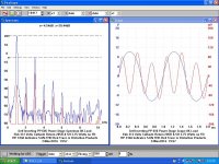
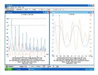
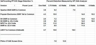
You are late to the party. I did an exhaustive series of tests early 2017 on the various versions of the self inverting power stage. More than 100 different combinations of cathode tail at several power levels. All would be better with a real phase inverter. Some were in use before WW2. Back then most anything sounded better than what was available a year before.
I've posted the results a few times on the forum since I did the work, some here may have already seen those.
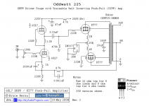
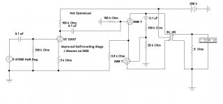
Recently there was an improved version posted on the forum. I wasn't able to find it so I've put an unoptomized version on so people can see what it looks like.
There are more images, later.🙂
I've posted the results a few times on the forum since I did the work, some here may have already seen those.
Recently there was an improved version posted on the forum. I wasn't able to find it so I've put an unoptomized version on so people can see what it looks like.
There are more images, later.🙂
Attachments
-
 Self Inverting PP 6V6s 3.75 Watts Choke Tail.JPG144.7 KB · Views: 129
 -
 6SL7-SRPP-KT77-Push-Pull-Tube-Amp-CCS.png28.1 KB · Views: 119
 -
 Simplified Self Inverting 6V6 PP Amplifier.JPG27.9 KB · Views: 79
 -
 LM317 Tail to Common Self Inverting PP Stage Oddwatt 225.jpg39.5 KB · Views: 80
 -
 NFET Tail to -22.4 Volts Self Inverting PP Stage.jpg42.7 KB · Views: 71
 -
 Screen Driven Self Inverting PP Stage Philco 37-640.JPG37.7 KB · Views: 91
 -
 117L7GT X2 PP Hifi.JPG89.9 KB · Views: 144
 -
 img20170203_19521701.jpg824.7 KB · Views: 161
 -
 Improved Self Inverting Stage.JPG43.7 KB · Views: 139
 -
 Self Inverting PP 6V6 Distortion.jpg118.6 KB · Views: 127
The 25L6 and 25L6-GT was made to be operated in Radios in single ended Beam Power mode, and with no negative feedback.
That is how it was able to put out 3.8 Watts at 9% distortion.
And the output transformer and loudspeaker were selected to make all that work reasonably well in those Radios. The loudspeaker parameters were selected to work with the amplifier that had far less than unity damping factor (DF <<1.0).
No, that complete radio system was not really Hi Fi.
Those Radios did not have power transformers, were directly powered off the mains power.
The radios were generally designed so that the only contact the user had with the radio was the insulated tuning knob, and the insulated volume control/on-off switch knob.
Contact with the chassis was forbidden (or you got Bit by electric shock).
Moving from that old single ended Beam Power radio amplifier to a self inverting push pull amplifier requires quite a bit of changes.
You would have to use a power transformer for the B+; you can not power your amp directly off the power line.
No exceptions, amplifiers have user contact with the input circuit, output circuit, and the chassis (it is not at all like the old radios the 25L6 and 25L6-GT were used in).
Prevent the "Surviving Spouse Syndrome" - Safety First!
The 25L6 (metal envelope) has a maximum plate voltage of 200V, and a maximum screen voltage of 117V.
The 25L6-GT (glass envelope) have a maximum plate voltage of 200V, and a maximum screen voltage of 125V.
If you do use the tube in self inverting push pull Beam Power mode, you will have a few watts, but a very low damping factor (the loudspeaker will see a high driving impedance).
That affects the frequency response of the amp/loudspeaker as a complete system.
It also makes most full range speakers and most woofers in 2-way and 3-way have flabby bass. The mid and high frequency response is affected too.
If you use the 25L6 or 25L-GT Beam Power tubes in triode wired mode, then
you might be able to use as much as 150V on the plate and screen that are tied together when in Triode wired mode.
But you will probably only get 2 or 3 clean Watts out.
Even though you can power the filaments directly off the mains power;
in all cases you have to use a power transformer for the B+.
Do not attempt to build such an amplifier, unless you really know what you are doing,
and all the details of making it work, and all the details of making it safe.
Unless you are in love with the 25L6 and 25L6-GT, and if you also are in love with the idea of building a self inverting push pull amplifier for simplicity, you will probably be much better served by using either EL84 Pentodes, 6BQ5 Beam Power tubes, or 6V6 Beam Power tubes for your power output tubes.
You are going to have to use a power transformer; most B+ power transformers you would use have both a B+ secondary, and a filament secondary (6.3V runs the output tubes filaments, and many useful input/driver tubes).
Be different than all the current up-to-date amplifiers.
Build what you want as long as it is safe, and it nominally works.
I have already seen all of the circuits and plots in Post # 26.
My self inverting push pull amplifiers do not use any of those circuits in post # 26, most of them are sub-par circuits, that is why they perform as advertised.
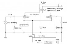
And yes, I like to use a different push pull topology now, the dual triode inverter with a solid state current sink, and push pull outputs.
That is my favorite now.
Oh, I left a well performing self inverting amplifier intact, it is too good to change it.
To each his own.
Build what you want as long as it is safe, and it nominally works.
I have already seen all of the circuits and plots in Post # 26.
My self inverting push pull amplifiers do not use any of those circuits in post # 26, most of them are sub-par circuits, that is why they perform as advertised.
And yes, I like to use a different push pull topology now, the dual triode inverter with a solid state current sink, and push pull outputs.
That is my favorite now.
Oh, I left a well performing self inverting amplifier intact, it is too good to change it.
To each his own.
Last edited:
I have already seen all of the circuits and plots in Post # 26.
My self inverting push pull amplifiers do not use any of those circuits in post # 26, most of them are sub-par circuits, that is why they perform as advertised.
Shew us your circuit.😀
My self inverting push pull amplifiers do not use any of those circuits in post # 26, most of them are sub-par circuits, that is why they perform as advertised.
Shew us your circuit.😀
Post #2 ??
f I remember correctly, a 25 Watt incandescent light bulb is very similar to a ballast. It has a very unstable resistance, depending on how much voltage you put across it. And that means an unstable current, as voltage is varied.
Say what?? A ballast is mostly an inductance, a 25W light bulb is a resistance. And stable soon as the operating temp is reached. Where ever did you get that information.🙄
jhjstewart9,
Yes, again you are absolutely correct.
I am sorry for the inaccurate statement that I made.
Ballast versus Ballast Tubes.
1. Ballasts are inductors for the old style fluorescent tubular light bulbs.
The same old style fluorescent light bulbs, that contain the same Verboten mercury substances that CFC lamps, mercury batteries, and old Thermometers contain.
You can also find mercury in rectifier tubes, and in medical offices in the old style blood pressure "meters" (a tube of mercury).
The old 1800s Tuna cadaver at the Smithsonian Museum had as much mercury in it as today's tuna.
Funny how a verboten substance gets grandfathered into our world.
Do not send any devices containing mercury through the US postal service. Verboten.
Do not send your mercury rectifiers by USPS.
I do not even know what shipping company would ship those mercury rectifiers if you told them they contain mercury.
The official legislation has a cleanup requirement for a CFC bulb that breaks on a rug in your house:
Open all windows and doors and exit the house for 15 minutes.
Call the hazardous material group that is assigned to clean up the remains of the CFC bulb.
They will come out and cutout a 3 by 3 foot section of your rug that contains the CFC bulb remains.
Then they will remove all that.
Oh, did I forget, congress in their infinite wisdom has not assigned funds for the hazardous materials removal group. There are no assigned hazardous material removal groups that will come to your house and remove broken CFC bulbs.
But if they removed the 3' x 3' carpet, the flooring company would like to come out to your house.
"If I were a Congressman, and if I were an idiot, but then I repeat myself" - Mark Twain /
Samuel L. Clemens.
2. I believe that (correctly or incorrectly) an old ballast tube used in old electronics is somewhat similar to an incandescent light bulb.
Perhaps that clears the difference between ballast and ballast resistor.
Oh, did I mention they are promoting Electronic Ballasts in stead of inductive ballets for fluorescent light tubes that still have mercury in them.
Efficiency, saved weight, and a whole new industry based on using devices that still contain mercury.
3. As old as I am, I am still capable of learning a thing or two.
Last edited:
jhstewart9,
I am already promised to draw and send a schematic of another one of my amplifiers to another poster on this Forum.
After I get the time to draw and send him the schematic, I may, or I may not, remember to draw and post the schematic of my self inverting push pull amplifier on this Forum.
Shew it indeed.
I love King James era language.
But I find our current language more full of puns; which I like even better.
Last edited:
jhjstewart9,
Yes, again you are absolutely correct.
I am sorry for the inaccurate statement that I made.
Ballast versus Ballast Tubes.
1. Ballasts are inductors for the old style fluorescent tubular light bulbs.
The same old style fluorescent light bulbs, that contain the same Verboten mercury substances that CFC lamps, mercury batteries, and old Thermometers contain.
You can also find mercury in rectifier tubes, and in medical offices in the old style blood pressure "meters" (a tube of mercury).
The old 1800s Tuna cadaver at the Smithsonian Museum had as much mercury in it as today's tuna.
Funny how a verboten substance gets grandfathered into our world.
Do not send any devices containing mercury through the US postal service. Verboten.
Do not send your mercury rectifiers by USPS.
I do not even know what shipping company would ship those mercury rectifiers if you told them they contain mercury.
The official legislation has a cleanup requirement for a CFC bulb that breaks on a rug in your house:
Open all windows and doors and exit the house for 15 minutes.
Call the hazardous material group that is assigned to clean up the remains of the CFC bulb.
They will come out and cutout a 3 by 3 foot section of your rug that contains the CFC bulb remains.
Then they will remove all that.
Oh, did I forget, congress in their infinite wisdom has not assigned funds for the hazardous materials removal group. There are no assigned hazardous material removal groups that will come to your house and remove broken CFC bulbs.
But if they removed the 3' x 3' carpet, the flooring company would like to come out to your house.
"If I were a Congressman, and if I were an idiot, but then I repeat myself" - Mark Twain /
Samuel L. Clemens.
2. I believe that (correctly or incorrectly) an old ballast tube used in old electronics is somewhat similar to an incandescent light bulb.
Perhaps that clears the difference between ballast and ballast resistor.
Oh, did I mention they are promoting Electronic Ballasts in stead of inductive ballets for fluorescent light tubes that still have mercury in them.
Efficiency, saved weight, and a whole new industry based on using devices that still contain mercury.
3. As old as I am, I am still capable of learning a thing or two.
What does most of this have to do with ballasts & incandescent light bulbs? Looks to me you are avoiding the issue.🙄
jhstewart9,
I am already promised to draw and send a schematic of another one of my amplifiers to another poster on this Forum.
After I get the time to draw and send him the schematic, I may, or I may not, remember to draw and post the schematic of my self inverting push pull amplifier on this Forum.
Shew it indeed.
I love King James era language.
But I find our current language more full of puns; which I like even better.
Bunk! You've got nothing. Better go back to peeling onions.🙄
PP 25L6 Guitar Practice Amp
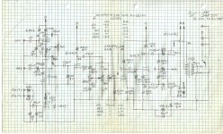
Much talk & no action! I built this one for a friend pre 1960. It manages a bit more than 6 watts. The PT used had a 170-0-170 volt HV secondary.
The Hammond 125D OPT tap is set for 4K. All built inside a Hammond 8x16x3 Steel Chassis, grey finish.🙂
Much talk & no action! I built this one for a friend pre 1960. It manages a bit more than 6 watts. The PT used had a 170-0-170 volt HV secondary.
The Hammond 125D OPT tap is set for 4K. All built inside a Hammond 8x16x3 Steel Chassis, grey finish.🙂
Attachments
Maybe this have been covered already but if not.
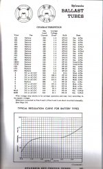
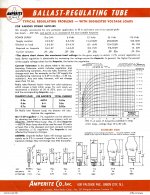
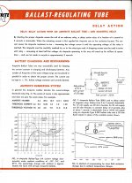
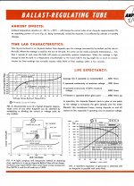
Ballast tubes, (or barretters) that was used to stabilise current was usually made with an iron wire and the tube was filled with hydrogen gas, as such it resembles an incandescent light bulb but current is more stable.
A typical ballast or barretter tube could keep current stable within 25 - 32 mA with a voltage drop varying between 130 and 230V, (data from GEC valve manual 1952)
Barretters are very slow devices so they will not work as a current source in an amplifier with audio frequencies. They where mainly used to stabillise heater current in series connected heater chains used in equipment directly connected to mains without power transformers.
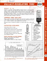
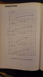
Some Ballast Tubes
There is more, I'll post it later.🙂
There is more, I'll post it later.🙂
Attachments
-
 Sylvania Ballast Tubes 12H 30C.jpg456.4 KB · Views: 84
 -
 Amperite Ballast Tubes p4.jpg613.1 KB · Views: 109
 -
 Amperite Ballast Tubes p3.jpg506.9 KB · Views: 100
 -
 Amperite Ballast Tubes p2.jpg513 KB · Views: 121
 -
 Amperite Ballast Tubes p1.jpg591.5 KB · Views: 107
 -
 Ballast Tubes.gif204.7 KB · Views: 75
This is not for guitar amps, but since I do play with a lot of tubes used in early cheap radio and turntable equipment it's not really HiFi I suppose either.
I used old radio tubes to make two guitar amps for a design challenge several years ago. The final version of these amps did have clean power amps, suitable for "almost HiFi" designs.
Back in 2011 a "discussion" was started when an Ebay seller came here to hawk his cheap guitar amp kit. He claimed that nobody could build a better design for less money. This prompted my two word reply, "Wanna bet?"
After a few insults were launched a third party proposed a challenge. Build the best guitar amp for less than $100 in documentable parts cost. The long, often heated, sometimes ugly, thread is now a sticky at the top of the Instruments and Amps forum, with some of the long insulting rants removed. Why? Several good amp designers built some nice low buck amps, often using unconventional techniques. It is a good informational thread with good tidbits of information hidden among the chatter.
This thread is often called the HBAC. Despite the rules clearly stated early on, several arguments from the Ebay seller about the definition of a "tube amp" ensued. It was declared that no silicon should be used anywhere in the amp, except in the power supply which was OK since his design used silicon diodes.
The Hundred-Buck Amp Challenge
I made two amp designs for this thread. The cheapest involved two circuits that directly apply to this thread.
Both designs used series heater string tubes designed for cheap table radios. I would NEVER apply raw line voltage to the heater string in such a design even if the B+ comes from a transformer. Heater to Cathode shorts are NOT uncommon and could result in line voltage on a guitar, or other user accessible component.....a deadly combination. Both designs used a novel power supply to heat the tubes and create B+.
I did an exhaustive series of tests early 2017 on the various versions of the self inverting power stage........All would be better with a real phase inverter.
The 4 tube amp I created for the HBAC used a pentode input stage, a single knob tone control a triode second stage and a self split output stage. The power transformer was a Triad N-68X isolation transformer and the OPT was a $4 Parts Express 70V line matching transformer. The amp met the challenge rules, played well, but didn't ROCK! It made about 2 watts on a good day. The schematic is posted below.
I used the amp a bit, but it got tossed into a box along with it's bigger brothers when I had to pack up everything and move twice for a total of 1200 miles. We had 3 weeks to get out of Florida, so things got misplaced. It resurfaced during a "box shopping" expedition 4 years later. I had sold or given away all of my guitar amps before the move, so I fired up the little amp.....Still didn't like it.
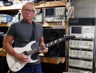
The challenge had ended and the HBAC thread had gone cold. I decided to make the amp into something that I would actually use, and still do. It can be seen in the picture on top of the speaker.
The new design was posted to the original thread along with my "Rules, we don't need no stinkin rules" statement, which wound up in post #1 slightly edited, and the thread became a sticky.
I decided that the little amp needed some mods......a little modding turned into a total rebuild. The remains of the original is on top of the RF spectrum analyzer to the right of my ear. The self split output stage got voted right out of the amp, replaced with a mosfet split load PI. "2 watts on a good day" turned into 4 watts at 3% THD (with a $4 OPT) and almost 6 watts at full crank. Second schematic.
I looked up Gyrator chokes, it looks like they could work well in a power supply but not so good as a plate choke, unless your intent is to add some distortion.
The input stage used an 18FW6 (like a 6AU6 or 6SJ7) but received a gyrator load. The gyrator can offer a very high load impedance while holding the plate voltage constant. Here the two resistors R6 and R7 form a voltage divider setting the plate voltage. The 2 meg pot adjusts the load impedance on the pentode from about 250K to 2.25 meg thus allowing for variable gain. At 250K the gain is sufficient to drive the amp into distortion from a guitar turned up full, but the stage is docile enough to deliver that 3% THD at 4 watts when fed a small signal from a sig gen. Turn that pot all the way up and the stage gain goes into the Soldano territory only limited by microphonics in the tube. The funky single knob tone control does all sorts of weird stuff depending on how hard it is driven.
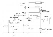
I posted the schematic for its big brother. The power supply used an isolation transformer to power the heaters and provide 170 volts for the screen grids and 340 volts for main B+. The circuit was based on an "Marshall 18 watt" design using 45B5's for output and 26AQ6's for preamp. Ignore all the silicon in the preamp schematic. it was an experiment that did not work and was bypassed in the final built except for the tone stack buffer.
I'm thinking about something like an octal preamp tube going to a pair of 25L6 PP self inverting. Series heated and I'm expecting something like 40-18K 7.5W with 9% THD. The 25L6 datasheet lists 9% distortion can you clear up what that really means?
The 25L6 and several other tubes are ALL 6W6GT's in disguise. Compare the tube curves, and maybe even smash a few dead tubes and compare guts, I did.
You can also find plenty 25L6 and 25W6 tubes with both numbers on them. The 6W6, 6DG6, 12L6, 12W6, 25W6, 25L6, and 50L6 are all identical except for heater ratings. The 6GC5 is also a 6W6 stuffed into a fat 9 pin bottle, while the 6DB5 is a 6W6 with smaller plates stuffed into a skinny 9 pin bottle.
The 12C5, 25C5, 50C5 and 50B5 are very similar tubes but have closer spacing to fit into a 7 pin bottle. ALL of these can make very good amps with some understanding of how and why all of these tubes have slightly different specs, and which spec can be ignored. The 35L6 and 35C5 are different tubes due to their lower power heater. They do not have the excess emission capability needed to be driven hard.
The spec sheets reflect the actual intended use of the tube. Yes, you can expect high THD if you run a single tube in SE class A and drive it hard enough to make nearly 4 watts with no feedback into a small OPT. These tubes were intended for line powered radios.
The same tube labeled 6W6 was intended for audio amps and TV vertical sweep duty. Here it gets a 300 volt plate rating with a 1500 volt peak voltage rating, a clue that the 200 volt maximum plate spec for the 25L6 is not real. Testing reveals this. I have run 25L6's and 6W6's to 425 volts on the plate and 120 volts on G2 where they make 35 watts at 3% THD while burning 15 watts per plate and 1.2 watts per screen grid.
Best results occur in the 300 to 350 volt range since the dissipation rating (which can be bent a little) becomes the limiting factor at high voltages. The 150 volt screen rating IS real and MUST be respected. Best results occur in the 110 to 130 volt range.
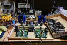
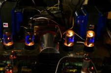
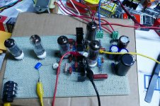
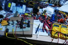
Wire a pair up to a decent set of OPT's and a good driver circuit capable of running them into AB2 and what happens. The picture shows exactly that, a box full of old 6W6's running on 300 volts into a pair of good 3300 ohm OPT's. I ran this test amp for several days both into a load and a pair of speakers. it works very well and makes 25 watts per channel at 3%THD (edge of clipping). The picture with the lights off reveal nothing glowing after running at 25 watts for several hours. I learned later on that running them at 340 to 350 volts into a higher impedance OPT (5K) gives more power at a slightly higher efficiency.
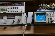
So how far can we push their little brothers? Here is the beginnings of a little guitar amp that uses 50C5's. The output stage successfully passed my "run it at full power overnight" test. It started the run at 20.0 watts and by the next morning the power was 20.03 watts.
Attachments
-
Schematic.pdf17 KB · Views: 116
-
GTA_4T_11-10.pdf22.6 KB · Views: 62
-
HBAC_5T.pdf29.1 KB · Views: 59
-
 NewGuitar_x.jpg862.3 KB · Views: 62
 -
 P1000471_x.jpg836.5 KB · Views: 68
 -
 P1000476light_x.jpg686.3 KB · Views: 63
 -
 P1000481_x.jpg652.8 KB · Views: 50
 -
 P3730052_x.jpg976.5 KB · Views: 66
 -
 P3730053_x.jpg195.3 KB · Views: 54
 -
 P3730057_x.jpg737.3 KB · Views: 58
- Home
- Amplifiers
- Tubes / Valves
- Ballast Tubes as a CCS