Those four caps (per channel) should be bi-polarised, I used Nichicon ES. I will check the BOM later today.
Update: checked the BOMs, they have the correct part number (UES1E100MDM) for those caps - it is a 10uF bi-polarized cap 5mm in diameter, lead space 2mm, Nichicon ES series. You can use anything that fits the board, of course.
Update: checked the BOMs, they have the correct part number (UES1E100MDM) for those caps - it is a 10uF bi-polarized cap 5mm in diameter, lead space 2mm, Nichicon ES series. You can use anything that fits the board, of course.
Last edited:
Sorry, my bad - I read "Electrolytic Capacitors" and my brain said -> "polarized". Your BOM is correct. Thanks for the clarification!
Pointless pedantry: its non-polarized, not bi-polarized. Bipolar or bipolarity is also used, implying symmetry (ie both poles equivalent), but _polarized_ means biased in one direction, so bi-polarized isn't a sensible construction.
Sample Arduino sketches to control each of the above mentioned digital volume controls (DS1882, MUSES72320, PGA2310 and WM8816) are now available on GitHub.
Nice Build! Is there any possibility to add a remote control via the Arduino-board for the Muses-variant? Do you have any code for this?
I have built a couple of prototype Arduino compatible control boards with rotary encoders and have been working, on and off, on the firmware. Turns out one can quickly put together something usable with a bunch of publicly available Arduino libraries. Making it work for a broader range of use cases and remote controls seems requires a bit more time and effort.
Tricky question... )) Which one from the boards get best (lowest noise) result?
1.Dual linear pot
2.WM8816/MAS6116
3.PGA2310
4.MUSES72320
1.Dual linear pot
2.WM8816/MAS6116
3.PGA2310
4.MUSES72320
Hi all
I have a USB DAC based on sa9227 + pcm5102a and a My_Ref Fremen Edition ampli based on LM3886.
I'm thinking to realize this preamp with some changes because I need also to attenuate the signal with a gain of about -15db
I would like to understand more information about the power section. I have some questions:
1. Is the power section shared between 2 channels?
2. Which trafo is needed? My idea is to use a 2x15V 50VA. Is it enough? Can I use a 2x12V 25VA?
3. for diode and capacitors I can use what suggested by original scheme of Bruno Putzeys?
Yes, the power supply for the preamp is shared between channels.
There are onboard +/-15V regulators for the two analog rails, and, in the digitally controlled versions, an additional +5V regulator for the digital supply. The +/- 15V regulators are cascoded with transistors to limit power dissipation and allow higher raw supply voltages.
The onboard regulators can be configured to work from a raw supply of between +/-18VDC (limited by the regulators' dropout voltage) to +/-40VDC (limited by the dissipation in the regulators and cascode transistors). For raw voltage below +/-25V, the cascodes need to be omitted. The analog regulators can be omitted altogether in case you want to use some external regulators. In any case, the board needs about 60mA on each rail, which is just over 2W at +/-18V raw supply.
Even though 50VA is excessive, your 2x15V trafo would work great if you omit the cascode transistors in the onboard power supply. 2x12V is too low for the regulators to work as is. You can still use it, however, by changing the regulators to 7812/7912 and omitting the cascodes. It will lower the rails to +/-12VDC and, although I did not test it, should work just fine.
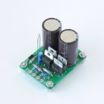
Any kind of reasonable rectifier and capacitors should work. I tested the board with a simple rectifier and a single 3300uF cap per rail (see photo). Bruno Putzeys added a second pair of capacitors and resistors, effectively cascading two RC low pass filters with the corner frequency of 72Hz, a simple and effective solution.
There are onboard +/-15V regulators for the two analog rails, and, in the digitally controlled versions, an additional +5V regulator for the digital supply. The +/- 15V regulators are cascoded with transistors to limit power dissipation and allow higher raw supply voltages.
The onboard regulators can be configured to work from a raw supply of between +/-18VDC (limited by the regulators' dropout voltage) to +/-40VDC (limited by the dissipation in the regulators and cascode transistors). For raw voltage below +/-25V, the cascodes need to be omitted. The analog regulators can be omitted altogether in case you want to use some external regulators. In any case, the board needs about 60mA on each rail, which is just over 2W at +/-18V raw supply.
Even though 50VA is excessive, your 2x15V trafo would work great if you omit the cascode transistors in the onboard power supply. 2x12V is too low for the regulators to work as is. You can still use it, however, by changing the regulators to 7812/7912 and omitting the cascodes. It will lower the rails to +/-12VDC and, although I did not test it, should work just fine.
Any kind of reasonable rectifier and capacitors should work. I tested the board with a simple rectifier and a single 3300uF cap per rail (see photo). Bruno Putzeys added a second pair of capacitors and resistors, effectively cascading two RC low pass filters with the corner frequency of 72Hz, a simple and effective solution.
Attachments
Thank you for the response.
Yes my idea is to use 2x12V with 7812 and 7912.
Due to low consuption of the board, another idea can be to reuse the trafo of the amplifier, puting the preamp in the same case. In this case I will have 2 trafo 2x24V, but I have to understand about possible connection problem.
I want use a potentiometer 10K. To have a negative gain I added a R = 27K before the potentiometer.
There are onboard +/-15V regulators for the two analog rails, and, in the digitally controlled versions, an additional +5V regulator for the digital supply. The +/- 15V regulators are cascoded with transistors to limit power dissipation and allow higher raw supply voltages.
The onboard regulators can be configured to work from a raw supply of between +/-18VDC (limited by the regulators' dropout voltage) to +/-40VDC (limited by the dissipation in the regulators and cascode transistors). For raw voltage below +/-25V, the cascodes need to be omitted. The analog regulators can be omitted altogether in case you want to use some external regulators. In any case, the board needs about 60mA on each rail, which is just over 2W at +/-18V raw supply.
Even though 50VA is excessive, your 2x15V trafo would work great if you omit the cascode transistors in the onboard power supply. 2x12V is too low for the regulators to work as is. You can still use it, however, by changing the regulators to 7812/7912 and omitting the cascodes. It will lower the rails to +/-12VDC and, although I did not test it, should work just fine.
Any kind of reasonable rectifier and capacitors should work. I tested the board with a simple rectifier and a single 3300uF cap per rail (see photo). Bruno Putzeys added a second pair of capacitors and resistors, effectively cascading two RC low pass filters with the corner frequency of 72Hz, a simple and effective solution.
So...
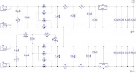
suppose to use a new trafo with secondary as 2x15 25VA and 7815/7915 as rectifiers, copying some schematics and taking into account your suggestion, this is my result. Wdyt?
Attachments
So...
suppose to use a new trafo with secondary as 2x15 25VA and 7815/7915 as rectifiers, copying some schematics and taking into account your suggestion, this is my result. Wdyt?
Yes, that's is what I had in mind.
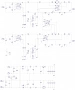
I had finalized the schematic and I'm finaliziing the PCB.
I'm using 1,5mm wires for ground, +15/-15V and 0,5mm for all others wires.
I think that this is enough or oversized, but I saw that the original PCB of Bruno Putzeys has a ground plane (I think so) on the bottom layer.
So now I have some doubts.
Can you help me?
I'm using 1,5mm wires for ground, +15/-15V and 0,5mm for all others wires.
I think that this is enough or oversized, but I saw that the original PCB of Bruno Putzeys has a ground plane (I think so) on the bottom layer.
So now I have some doubts.
Can you help me?
Ok.
Is this needed, suggested or...?
I need to add it to my PCB?
More general question, how I should configure my wires size?
Is this needed, suggested or...?
I need to add it to my PCB?
More general question, how I should configure my wires size?
You need a ground plane, however ground-connected signal references must be kept separate and connect to the ground plane at a single point.
The wire size is relatively unimportant. The BPPBP board uses 0.5mm for power supply, 0.2mm for signals and a solid ground plane.
Did you read Bruno Putzey's article?
The wire size is relatively unimportant. The BPPBP board uses 0.5mm for power supply, 0.2mm for signals and a solid ground plane.
Did you read Bruno Putzey's article?
Last edited:
You need a ground plane, however ground-connected signal references must be kept separate and connect to the ground plane at a single point.
The wire size is relatively unimportant. The BPPBP board uses 0.5mm for power supply, 0.2mm for signals and a solid ground plane.
Did you read Bruno Putzey's article?
Yes, I read it. Honestly the teory is clear, but the practice...
For example the sentence "When you have a chain of signal processing stages laid out on a board with a solid ground plane, each signal run between stages is referenced at the most convenient point on the ground plane."
I think this is the theory and your sentence "however ground-connected signal references must be kept separate and connect to the ground plane at a single point." is the practice.
I will try to follow your suggestion and eventually I will post the result here.
Thanks again
So...
I hope to not become off topic.
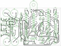
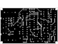
I created a ground plane on the bottom layer and all components that refer to the ground are directly connected to that plane.
All other wires are on the top layer except for that ones that can only be created on the other side.
In attach the schematic and the result of my job.
I hope to not become off topic.
I created a ground plane on the bottom layer and all components that refer to the ground are directly connected to that plane.
All other wires are on the top layer except for that ones that can only be created on the other side.
In attach the schematic and the result of my job.
Attachments
- Home
- Source & Line
- Analog Line Level
- Balanced Volume Controller / Line Stage