Depending on speaker placement, absolutely!! 3 - 6db is most certainly detectable by the human ear!
Tony.
Tony.
Do you mean the step in the frequency response due to the transition from 2 pi to 4 pi radiation or do you mean diffraction ripples due to diffraction from cabinet edges?
Even if the response is made flat electronically, diffraction can be audible. Not to mention what its presence represents. However, modifying the response on an otherwise finished product is a logical step.
Even if the response is made flat electronically, diffraction can be audible. Not to mention what its presence represents. However, modifying the response on an otherwise finished product is a logical step.
How does it present itself? A drop in loudness?
Do you mean the step in the frequency response due to the transition from 2 pi to 4 pi radiation or do you mean diffraction ripples due to diffraction from cabinet edges?
Yes, I’m referring to cabinet edge design. I’ve read about radiused edges being “ the way to go” but manufacturers like Harbeth have squared edge baffles. So what gives?
I'll tell you what I know about diffraction and bafflestep, Nigel.
Let's take a typical closed box 8" bass plus 3/4" tweeter speaker like my current crossover project:
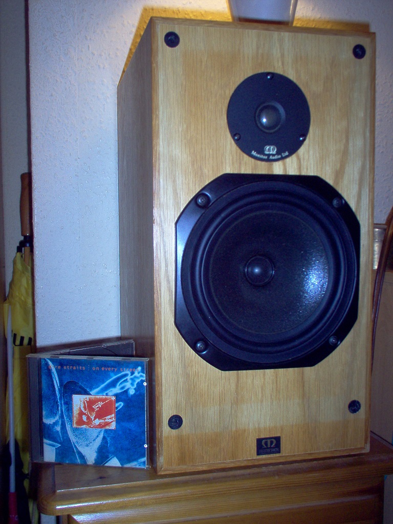
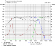
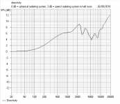
It's the nature of waves like sound that they are affected by nearby surfaces and edges. What happens with this speaker is that below 300Hz, the waves find their way in all directions, even backwards. Above 300Hz, most of the sound finds its way forwards. The directivity plot is all about diffraction effects. You can see the 6dB rise around 300Hz.
This means the higher frequencies actually sound louder in the forward direction than the bass. Actually 4X the power or 6dB loudness. This is a bit like a car having 4X the energy at 60mph as 30mph. Strange but true.
There's a bit of effect from the wall behind. If the speaker is close to a wall, the bass is a bit louder, because there is a reflection back.
Bottom line is I had these speakers working nicely to my ears, but a listening friend asked where the bass was. I decided to boost the bass a bit to get nearer what people are used to.
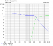
It was easy enough to adjust the bass coil up, and the shunt coil down so the bass was louder relative to the midrange. Strictly speaking, tweeter level needed taking down too. Notice that electrically I only apply 3dB of bafflestep. The rest of the theoretical 6dB is built into the bass unit and the room acoustic.
Diffraction effects with rounded corners on cabinets are only going to affect the highest frequencies. 3kHz is 5cm half wavelength. A 2cm chamfer won't do much there. I don't think it'll do much to any other frequencies on a 27cm wide cabinet either. The old rectangular box works well enough, IMO.
When you build a speaker into a wall, as studios often do, neither bafflestep or diffraction has any effect at all.
Let's take a typical closed box 8" bass plus 3/4" tweeter speaker like my current crossover project:
It's the nature of waves like sound that they are affected by nearby surfaces and edges. What happens with this speaker is that below 300Hz, the waves find their way in all directions, even backwards. Above 300Hz, most of the sound finds its way forwards. The directivity plot is all about diffraction effects. You can see the 6dB rise around 300Hz.
This means the higher frequencies actually sound louder in the forward direction than the bass. Actually 4X the power or 6dB loudness. This is a bit like a car having 4X the energy at 60mph as 30mph. Strange but true.
There's a bit of effect from the wall behind. If the speaker is close to a wall, the bass is a bit louder, because there is a reflection back.
Bottom line is I had these speakers working nicely to my ears, but a listening friend asked where the bass was. I decided to boost the bass a bit to get nearer what people are used to.
It was easy enough to adjust the bass coil up, and the shunt coil down so the bass was louder relative to the midrange. Strictly speaking, tweeter level needed taking down too. Notice that electrically I only apply 3dB of bafflestep. The rest of the theoretical 6dB is built into the bass unit and the room acoustic.
Diffraction effects with rounded corners on cabinets are only going to affect the highest frequencies. 3kHz is 5cm half wavelength. A 2cm chamfer won't do much there. I don't think it'll do much to any other frequencies on a 27cm wide cabinet either. The old rectangular box works well enough, IMO.
When you build a speaker into a wall, as studios often do, neither bafflestep or diffraction has any effect at all.
Attachments

Let's take a typical closed box...
Thanks for that Steve, it all makes a little more sense to me now.
It's a very vague correction really and it confuses the heck out of most people.
The usual method is the big bass coil:
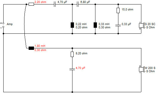
You really need a simulator to do it this way.
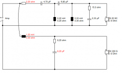
The other way, rather unfashionable, is to use a passive bafflestep adjustment, here 1mH and 2.2R for about 2dB.
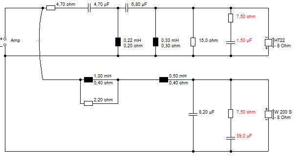
This circuit is bass impedance corrected, so you use rather textbook values for the actual second order rolloff. It is how you might get a reasonable result from one of those much-maligned online calculators:
2-Way Crossover Calculator / Designer
The usual method is the big bass coil:
You really need a simulator to do it this way.
The other way, rather unfashionable, is to use a passive bafflestep adjustment, here 1mH and 2.2R for about 2dB.
This circuit is bass impedance corrected, so you use rather textbook values for the actual second order rolloff. It is how you might get a reasonable result from one of those much-maligned online calculators:
2-Way Crossover Calculator / Designer
If you put any driver on an infinitely large baffle it will have amplitude variation.
One thing we try and do as designers is to match the baffle shape and driver placement on said baffle to "offset" the peaks and dips "native" to the driver.
In reality - what might work for placement for a tweeter and mid-woofer in isolation cannot be combined (or they might sit in the same or overlapping place on the baffle, or not in the same vertical axis etc...)
a 3dB variation is audible - with a caveat of where it is in the frequency spectrum (equal loudness curves) and width of the "peak or trough".
All the above can be simulated to get you in the ballpark. I use a baffle diffraction simulation spreadsheet.
It presents as an audible silhouette of the outline of the sharp edges. It is due to the time delay of these extraneous sources and the different angle of them to the direct sound. Further, this not specifically controlled sound can contribute to reflected sound that doesn't match the direct sound in response.How does it present itself? A drop in loudness?
A flat response can be an indication of a lack of problematic diffraction but not the other way around, necessarily. Hence the benefit of polar measurements.
That was a cracking video on diffraction, Nigel!
YouTube
Enjoyed that. Seems like baffle width is the main event, and diffraction is really a low priority issue.
I think the guy is called Ryan, and he has a great channel:
YouTube
He visits Planet10's, aka our own illustrious Dave, place for a bit of fullrange listening in one of the videos. I was enthralled by the crossover reviews video for his S5 speaker, naturally. 😱
I looked up the drivers for this bookshelf:
5" SB13PFC25-4 :: SB Acoustics
Vifa XT25SC90-04 Ring Radiator
Better than the usual mismatched trainwreck of drivers people usually bimble up to this forum with. In fact the XT25SC gets huge recommendation from him as being good and cheap. The cheap SB looks quite well-behaved too. 😀
YouTube
Enjoyed that. Seems like baffle width is the main event, and diffraction is really a low priority issue.
I think the guy is called Ryan, and he has a great channel:
YouTube
He visits Planet10's, aka our own illustrious Dave, place for a bit of fullrange listening in one of the videos. I was enthralled by the crossover reviews video for his S5 speaker, naturally. 😱
I looked up the drivers for this bookshelf:
5" SB13PFC25-4 :: SB Acoustics
Vifa XT25SC90-04 Ring Radiator
Better than the usual mismatched trainwreck of drivers people usually bimble up to this forum with. In fact the XT25SC gets huge recommendation from him as being good and cheap. The cheap SB looks quite well-behaved too. 😀
Last edited:
Hi Steve, with your explanation yesterday and after watching his video I understand the problem much better. As for driver selection; I’ve got four BM220.8 woofers kicking around. I was going to pair them with some scanspeak D2905/970000’s but after reading a couple of your posts, I’ve decided to try some Seas 27TBFC/G H1212 instead. I just need to learn how to sim them now.
Do we mean the Volt 228.8?
H1212-06 27TBFC/G
Volt Loudspeakers | BM228.8 (8″)
Looks a nice combination. 😎
Joachim Gerhard has a lot of time for that tweeter too:
Sonics by Joachim Gerhard cabinets and kits.
I'd like to try that tweeter myself. I'm using a ferrofluid SEAS 19TAF/G metal 19mm currently. But this unfussy 3kHz crossover for the well-behaved 8" is excellent. I think it would work with your drivers with a bit of tweeter attenuation. As long as the tweeter is flattish, the 4th order filter dominates and most stuff works.

Always room to fiddle around for fine tuning. It's why you have to listen to a speaker no matter how good the sim.
H1212-06 27TBFC/G
Volt Loudspeakers | BM228.8 (8″)
Looks a nice combination. 😎
Joachim Gerhard has a lot of time for that tweeter too:
Sonics by Joachim Gerhard cabinets and kits.
I'd like to try that tweeter myself. I'm using a ferrofluid SEAS 19TAF/G metal 19mm currently. But this unfussy 3kHz crossover for the well-behaved 8" is excellent. I think it would work with your drivers with a bit of tweeter attenuation. As long as the tweeter is flattish, the 4th order filter dominates and most stuff works.
Always room to fiddle around for fine tuning. It's why you have to listen to a speaker no matter how good the sim.
Last edited:
Do we mean the Volt 228.8?
H1212-06 27TBFC/G
Volt Loudspeakers | BM228.8 (8″)
Looks a nice combination. 😎
Joachim Gerhard has a lot of time for that tweeter too:
Sonics by Joachim Gerhard cabinets and kits.
I'd like to try that tweeter myself. I'm using a ferrofluid SEAS 19TAF/G metal 19mm currently. But this unfussy 3kHz crossover for the well-behaved 8" is excellent. I think it would work with your drivers with a bit of tweeter attenuation. As long as the tweeter is flattish, the 4th order filter dominates and most stuff works.
Always room to fiddle around for fine tuning. It's why you have to listen to a speaker no matter how good the sim.
Actually Steve, the 228.8 is a revision of the 220.8.
Attachments
It's why you have to listen to a speaker no matter how good the sim.
I don't have to listen common speaker concepts, but it is fun part of the project and might give some experience for the future. Unfamiliar concepts need listening and tuning for studying how simulation should be.
- Status
- Not open for further replies.
- Home
- Loudspeakers
- Multi-Way
- Baffle step diffraction