Pulsating sphere has a critical frequency w = Co/R, where w = 2pi*f, Co = 340m/s and R is the sphere radius. Radiating impedance (simplified) is radiating mass m in parallel with radiating resistance r, connected to common force F.
Normalised radiating impedance is Znv = jkR/(1 + jkR), Znv = A + jB
A = (kR)*2/(1 + (kR)*2)
B = kR/(1 + (kR)*2)
.... and the well known plots with kR as a parameter.
If R is large then kR is large and the real term - the radiating one - is unity in that limit. In the near field it's quite different of course, but we are almost always in the far field where the real part approaches one and the imaginary part approaches zero.
Of course this is not a solid argument either way since the actual radius of the source must be know and we could never build a pure spherical source anyways. But if R >> a (the source radius) then the radiation is unity for most of the audio band above some LF TBD.
Last edited:
I don't know. If I was going to illuminate the room I guess I'd rather do it on purpose and in a more thorough manner. I think there would be a lot of trial and error but, I suspect that with a good radial to start some of that trial and error might be done through placement.Why? I would have thought dipole would be a better compromise between directivity and spaciousness (ambience)
Rather than raytracing a small reflector (chimney flue rain cap type), what about using a pair of small drivers mounted above and below radial elements? There is not much out there to compare with it.
I don't know. If I was going to illuminate the room I guess I'd rather do it on purpose and in a more thorough manner. I think there would be a lot of trial and error but, I suspect that with a good radial to start some of that trial and error might be done through placement.
Rather than raytracing a small reflector (chimney flue rain cap type), what about using a pair of small drivers mounted above and below radial elements? There is not much out there to compare with it.
Here is a baffle less speaker design using PVC. He says the imaging is almost spooky its so good. Probably a lot of ambience as well. A design like this is hard to pull off in a passive system though.
Tubifex - undefinition
A lot of omni's score poorly in imaging by reviewers. I think its the lack of direct sound. If the direct sound is there without early reflection it should image. But the earlier the speaker transitions to direct sound might help it image in the low frequencies.
Why are two subwoofers better than one, unless the two sources in some way average the sound? This might not be imaging per se but the effect is similar.
Last edited:
Speculating, I'd say there is no proper geometric entry point into the room.....
Really? Below is a link to what Linkwitz has to say on the subject. I like Linkwitz and read (and try to understand in full) his many publications in reputable journals. Like the link I attached earlier, he struggles with the reality of reproducing music in domestic settings and trying to capture the essence with his physical measurements.
The-Magic-in-2-Channel-Sound
B.
Last edited:
Spooky is an interesting word. I'd associate it with the sound of low DI speakers. When a high DI speaker images I wouldn't call it spooky, I'd call it relaxing because it is there without having to think.imaging is almost spooky its so good.
@Ben
As I also mentioned, one would have to be found. Linkwitz recognised that sufficiently delayed reflections can be acceptable.
Interestingly too, his later incarnation of baffle became smaller and less regularly shaped.
As I also mentioned, one would have to be found. Linkwitz recognised that sufficiently delayed reflections can be acceptable.
Interestingly too, his later incarnation of baffle became smaller and less regularly shaped.
Smaller because ultimately it's best not to have one at all, but then requires more drivers and more eq. Irregularly shaped to spread out the diffraction effects. Although looking at his real world measurements the diffraction irregularities art as bad as predicted by the maths.
Has anyone devised a boxless omni?
Has anyone devised a boxless omni?
A boxless omni would just be a point source. You can make a point source by covering a sphere with sources, for example.
I assumed Linkwitz had also wanted to make the diffraction sources closer together (is that what they call precedence effect).
I assumed Linkwitz had also wanted to make the diffraction sources closer together (is that what they call precedence effect).
I don't subscribe to this. Unless the source is small, it is going to display some kind of dipole effect around some frequency.Smaller because ultimately it's best not to have one at all
The pair of mic's in Row H is picking up the total sphere of sounds, not a beam of sound coming from somewhere that can't quite be defined. So wouldn't it make sense to release that feed back into your room as a sphere?
There's nothing more natural about (1) shooting sound like a flashlight beam from a baffolded speaker to your chair than (2) shooting the sound about in all direction but originating from a dipole.
B.
There's nothing more natural about (1) shooting sound like a flashlight beam from a baffolded speaker to your chair than (2) shooting the sound about in all direction but originating from a dipole.
B.
I meant the ripples above the dipole peak reduceI don't subscribe to this. Unless the source is small, it is going to display some kind of dipole effect around some frequency.
Anyone tried the Power Cepstrum to evaluate the audibility of diffraction?
Bill Waslo has included it in at least 2 versions of his software and has a write-up on it on his web page here. Reflecting on Echoes and the Cepstrum
Peter
Bill Waslo has included it in at least 2 versions of his software and has a write-up on it on his web page here. Reflecting on Echoes and the Cepstrum
Peter
That's an interesting idea, but I have never looked at cepstrum as having any different information than the impulse response, in fact it actually has a little less. Remember that both the cepstrum and the impulse response are Fourier transforms of the frequency response, but the cepstrum does not retain the phase and just uses the frequency response magnitude. I don't see why throwing away the phase would yield anything more than the impulse response does. It might show some things "different" and maybe that could be enlightening, but I would not guess that it would shine a much brighter light on the situation.
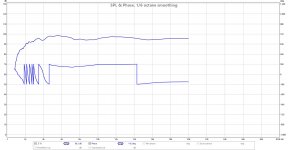
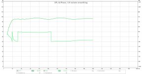
This was done with a SS d2604 soft dome at 36" from an active 4th order xo. I am quite surprised at how much worse it is in the 2k-3k range. To be fair the blue one is partially surface mounted in a 2 way box (round tweeter set in an old accuton square cut out) has 1/2" round edges on the sides and the box is setting on another speaker box that is sticking out 1.75". ugly. And the green is mounted to a squat baffle (6" tall) w/ chamfered top and bottom 30 deg. and curved sides with a 2.5" radius and no box sticking out below. Not the point really to go into the boxes but FYI... critical range for the tweeter...
Attachments
Remember that both the cepstrum and the impulse response are Fourier transforms of the frequency response, but the cepstrum does not retain the phase and just uses the frequency response magnitude.
More precisely, impulse response is an inverse Fourier transform of the (complex) frequency response.
Regarding cepstrum, there is a type known as the "Complex Cepstrum" (Oppenheim et al., Nonlinear Filtering of Multiplied and Convolved Signals, IEEE Trans. Audio & Electroacoustics, vol. AU-16, No. 3, Sept. 1968). Despite its name it is a real valued function, but, unlike the power cepstrum, the complex cepstrum is obtained from the complex spectrum, with no loss of phase information.
If R is large then kR is large and the real term - the radiating one - is unity in that limit. In the near field it's quite different of course, but we are almost always in the far field where the real part approaches one and the imaginary part approaches zero.
Of course this is not a solid argument either way since the actual radius of the source must be know and we could never build a pure spherical source anyways. But if R >> a (the source radius) then the radiation is unity for most of the audio band above some LF TBD.
I think we should make a clear distinction between the spherical wave and the spherical source. The formulas of the radiation impedance I have shown were for the spherical source, thus R was the sphere radius. I know it is confusing, because in some texts we find R and elsewhere a for the sphere radius, and r for the distance from the source. However, the critical frequency of the spherical source, where kR = 1; is f = c/(2pi.R), it applies for R as a sphere radius, and there is a change in frequency response of the spherical source just at this critical frequency, determined by the sphere radius.
Otherwise I agree with your post, of course.
Hi Pavel
Yes, I mean Inverse Fourier transform.
Yes, I see now what you meant - the sphere has a HP function to its radiation impedance at some LF point depending on the spheres size. But a piston has the same thing. The difference being that the pistons polar response narrows at HFs allowing for a flat axial response, while the sphere does not, meaning that its axial response (everywhere) will fall. This is exactly the same effect that a waveguide has if its radiation is spherical.
Hi Earl,
yes, exactly.
First time when I wrote about directivity of the spherical source I made a mistake, a mistake based on terminology, when I exchanged pulsating sphere for an oscillating sphere. Oscillating sphere moves in a line just in one direction (radius unchanged) and IS directional. Pulsating sphere changes radius everywhere on its surface and is, of course, omni-directional. Difficult to produce, of course 🙂. I remember B&K produced a "quasi-spherical" source based on 12 conventional drivers placed on sphere-like surface.
When using horns ....
Just a reality check on the need for minimizing baffle diffraction (Are heroic efforts needed since they make the design and construction potentially much more constrained and difficult?). Many of the contributors seem to be using two-way systems (12 or 15 inch woofer) and a horn tweeter (crossed typically between 700-1000Hz)
As far as the woofer goes the wavelength are going be at 13 inches or larger. Any perturbation produced by a cabinet edge or grille (reasonably constructed) is going to be very small compared to the wavelength.
As far as the horn tweeter. These are typically launching the waveform with a horizontal dispersion 90 degrees (plus/minus 45 deg) or in rarer cases 60 degrees.
So I understand the concern about diffraction for cone speakers, but isn't this one of the reasons (amongst others) for using horn top sections? Why the worry?
What am I missing?
- Home
- Loudspeakers
- Multi-Way
- Baffle Diffraction