Just a little reminder: If your output stage is a gain-of-one buffer (like M2 or F4), and especially if your output stage has a gain less than one (like VFET or SIT), then you want a front end with very wide output swing. Or else the front end will go into clipping before the output stage, which is terrible because you won't get as much undistorted output power as your output stage's power supply could deliver.
That's why some VFET / SIT front end cards (Marauder, Dreadnought, Lexington) include a DC-to-DC converter, giving a boosted power supply and therefore wider output swing from the front end.
That's why some VFET / SIT front end cards (Original Lottery Amp FE , Scourge, Bulwark, Kitty Hawk, Nimitz etc) include a step-up transformer at the output, giving wider output swing from the front end.
Why is -In capacitor coupled? Is that to allow for mismatches of JFET Idss?pinout for 2SK170, 2SK370, LSK 170, 2SK2145
J113 - manage, isolator bushing on one pin is solving rotation of same, if needed
same applies if you want to use BC639/40 instead of ZTX
depending of rails voltage, resistor or two needs change of value, trivial
you know that is, in most cases, having protection duty
allowing some leeway regarding DC offset of upstream component
with or without, and you know how, who cares
allowing some leeway regarding DC offset of upstream component
with or without, and you know how, who cares
But In+ is DC coupled, and an large upstream DC offset will still cause problems. The asymmetry between In+ and In- has be baffled.you know that is, in most cases, having protection duty
allowing some leeway regarding DC offset of upstream component
with or without, and you know how, who cares

But In+ is DC coupled, and an large upstream DC offset will still cause problems. The asymmetry between In+ and In- has be baffled.
it's done exactly like that for eons
of course that excessive upstream DC is going to result in problems
but - role of that cap is to prevent amp of amplifying moderate DC on its inputs
safest and trouble-free amp is - no amp at all ......... sit by the river or ocean ....... and enjoy

If "excessive upstream DC" could be a problem, why capacitor couple In+ also? The output of the preamp is then gain*(ac(In+)-ac(In-)), since R2 references to output to ground. Papa's BAF2022 video show the highly simplified Stasis front-end with capacitors on both inputs. https://www.diyaudio.com/community/threads/baf2022.391289/post-7182649
well, shoot him, not poor Messenger
you know Papa's advice, when dealing with everything - ".... do it in halfsteps....... "
probably next Stasisssss FE will have both inputs cap coupled ....... or none

now seriously - best remedy for excessive upstream DC is - bullet in head of operator
and you need completely other sort of gadgetry for that
you know Papa's advice, when dealing with everything - ".... do it in halfsteps....... "
probably next Stasisssss FE will have both inputs cap coupled ....... or none
now seriously - best remedy for excessive upstream DC is - bullet in head of operator
and you need completely other sort of gadgetry for that
Both. Jumper wires across the caps can convert to none or one.probably next Stasisssss FE will have both inputs cap coupled ....... or none
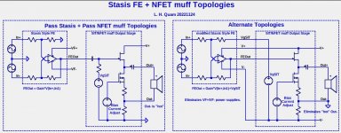
I propose one more change to the next Stasisssss FE: Do not ground R2 (100k) -- allow R2 to connect to an external input as will be illustrated below. With that change and both inputs cap coupled, the Stasisssss FE can use the same power supplies as the OS and do some other tricks as well, which I will illustrate in a future post.
Attachments
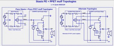
The second one looks like not correct. V- is short to GND only thru a small R. The big cap have to be moved to the negative terminal of speaker.
It is correct. The power supply floats by the voltage across that resistor.The second one looks like not correct. V- is short to GND only thru a small R. The big cap have to be moved to the negative terminal of speaker.
Both. Jumper wires across the caps can convert to none or one.
I propose one more change to the next Stasisssss FE: Do not ground R2 (100k) -- allow R2 to connect to an external input as will be illustrated below. With that change and both inputs cap coupled, the Stasisssss FE can use the same power supplies as the OS and do some other tricks as well, which I will illustrate in a future post.
going Papa's overindulging route?
It is still a muff. The reason this works depends on the Stasis opamp having cap coupled inputs and a decent of common-mode rejection ratio (CMRR). The AC swing on the supply is actually small: Vout*R2/Rload, which is Vout/40 for R2=0.2R and Rload=8R. The output stage doesn't care about the location of the ground connection. I have run extensive simulations of this and it works just fine, having exactly the same performance as with ground connection to V-.Should the speaker negative be connected GND? Is it still a MuFF?
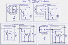
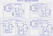
Here are more Stasis FE and muff topology options for both PFET and NFET configurations. I am particularly interesting is the differential amp bias servo because it provides more options for R1 and R2 of the mu follower. The R1 and R2 can be chosen to provide better performance, lower overall power dissipation, and higher output. More about that in a future post.
Attachments

- Home
- Amplifiers
- Pass Labs
- BAF2022