That's super helpful information! Thanks for sharing. Sounds like the ripoles can sit reasonably close to the wall, which is pretty flexible.

That's super helpful information! Thanks for sharing. Sounds like the ripoles can sit reasonably close to the wall, which is pretty flexible.
You welcome @dayneger !
Here's an interview of Axel Ridtahler, published on the lautsprechershop.de website. Notably, Mr. Ridtahler describes the radiation pattern of the ripole principle, and its advantages on the bass coupling with the room :
The best explanations on Ripole subwoofers operation, given by the inventor himself... 😉
Here are the dimensions of my MICRO Ripole (mm). As you can see, it was very compact :
And it would have been a cool project, indeed, if not ruined by that poor and lousy performance LPF micro sub module - to avoid and discard, despite it had the perfect size... 😡 🙁
I know that a few years ago, a member on DIYaudioprojects followed my footprints by building a pair of my MICRO Ripole design, with a 3-D printer (yes !), and he told me that he met the expected success, because he had an external active Xover in his system, set to compensate the LPF flaw of the micro-sub module.
T
Here's an interview of Axel Ridtahler, published on the lautsprechershop.de website. Notably, Mr. Ridtahler describes the radiation pattern of the ripole principle, and its advantages on the bass coupling with the room :
The problem with Axel's explanation is that the RiPol, (or "W Frame dipole") or whatever you prefer to call it does display the same radiation pattern as a dipole in the subwoofer range of operation.The best explanations on Ripole subwoofers operation, given by the inventor himself...
This can be clearly seen in MalVeauX outdoor measurements, the on-axis front and rear radiation of his subwoofer is virtually identical below 100Hz:
Hi all,
I completed a fun project using some concepts I've been learning and throwing around ideas with and wanted to test some things and try a few new things and it gave me something to work on through the hurricanes instead of wondering what it would be like to use my subs as canoes after being washed away in hurricanes (I'm in Florida). Finished this one up and just wanted to share the results because its different and probably about as DIY as it gets in many ways. So I hope you can come by an take a laugh at it or maybe some interest in it, either way, as I went to clown town on this...
I completed a fun project using some concepts I've been learning and throwing around ideas with and wanted to test some things and try a few new things and it gave me something to work on through the hurricanes instead of wondering what it would be like to use my subs as canoes after being washed away in hurricanes (I'm in Florida). Finished this one up and just wanted to share the results because its different and probably about as DIY as it gets in many ways. So I hope you can come by an take a laugh at it or maybe some interest in it, either way, as I went to clown town on this...
- MalVeauX
- Replies: 26
- Forum: Subwoofers
The 90 degree off-axis reduction in level show the clearly defined dipole RiPol "figure of 8 pattern".
For a deeper understanding of dipole radiation and it's effects in room, this dipole and uframe thread has lots of good information:
Perry Marshall's Live Edge Dipoles inspired me to study them with the aim of developing my own variation on the theme. To do so, I had to develop Vituix models for the dipoles and for the Uframe, which I'd like to share. Perhaps someone can compare model predictions against their speakers.
Dipole modeling in Vituix is well known but running the model made clear that with dipole coax drivers, the coax mid woofer cone was being used over a much wider range than done in multi-way open baffle speakers and that there were consequences to that.
A U-frame model starts the same as a dipole...
Art
@tubelectron, your little ripoles got me thinking about a smallish one to pair with my son's upcoming bookshelf speakers!
I didn't want to hijack this thread anymore, so I started a new one here:
I didn't want to hijack this thread anymore, so I started a new one here:
Having recently seen @tubelectron's micro and miniripole designs, it inspired me to play around with different variations to pair with my son's future bookshelf speakers, which are expected to be Zaph ZA5.2s (thanks for the midwoofers, @mordikai!) that could benefit from support below 80 Hz. I'm not looking for high SPL or shaking the whole house, but playing down (to ideally below 30 Hz) at modest volumes would be pretty sweet.
I'm swinging from cheap and cheerful to slightly better but still inexpensive drivers arranged in different ways. It seems that a downside is that...
I'm swinging from cheap and cheerful to slightly better but still inexpensive drivers arranged in different ways. It seems that a downside is that...
- dayneger
- Replies: 9
- Forum: Subwoofers
The problem with Axel's explanation is that the RiPol, (or "W Frame dipole") or whatever you prefer to call it does display the same radiation pattern as a dipole in the subwoofer range of operation.
Below, we have a comparison of a Sealed 340L, 1m² Open Baffle and 430mm cubic Ripole configurations :
T
@weltersys as I recall, onr of the main benefits of the ripoles is the extension of the lower frequencies. And a certain smoothness in the sound.
I went from a boxed sub to a repole with my open baffles. I like the smoothness. But still, they are to small for real output at the low end, even though they do go lower than the subs I had. That has to change this time. I was thinking about the modern low frequency subs, but the arguments about the sound in the posts prior made me focus back too ripoles.
On which I came across another issue. Calculation.
Rithaler himself says that a rule of thumb doesn't work. But it seems a lot of his calculations is about the crossover and resonance. At least thats my impression.
CharlieM has a rule of thumb:
Area of front chamber opening should be 1/3 to 1/4 of woofers’ combined piston area (SD).
For woofers having more than 10mm X-max, use 1/3 SD minimum.
For woofers with 10mm or less X-max, chamber area can be 1/4 SD.
Area of rear chamber opening should be 1/2 to 1 SD.
If I look at commercial German ripoles, I wonder. Lautsprechershop has a half ripol with a 0,2 x sd2 on +-6mm xmax. Visatons petit orgue has on the 6mm xmax 0,41 x sd2. Thats more than double the area.
So, where does that leaves us?
@hjo, to give you an idea about my Omega Ripole 2x12"
This gives the following ratios :
T
- one BEYMA 12BR70 speaker has SD=540cm2
- the common front opening is SF=364cm2
- one of the two back openings is SB=262cm2
This gives the following ratios :
- common front opening = 364/(2x540)=0.337 combined SD, so roughly 1/3
- one back front opening = 262/540=0.485 SD, so roughly 1/2
T
To verify this theory and optimize the dimensions of my Ripole, I built a prototype. I made measurements with the outlet reduced using rigid plates (in pink). Here are the curves for an opening varying from 7 to 13 cm here 7 and 10. The size of the outlet is not critical, unless we exaggerate. In blue, the curve with correction.
CharlieSo, where does that leaves us?
You could model the frequency response (and directivity) of whatever configuration you would like using Hornresp:
http://www.hornresp.net/
Explanations on the how to model the RiPole can be found in various threads:
Hi @David McBean
I’m getting to grips with using Hornresp to simulate Ripoles. I used your example of the settings for a Ripole and they make sense, with the front port being made up of 2 x the smaller volume and each rear port being the larger volume. The target being the smallest possible volume to move the resonance peak as far up the frequency range as possible (>300hz if possible)
I have attached your original screenshots from post #13372 which I used as the basis of entering the data for a Ripole.
My main issue is how to convert the settings into actual construction...
- GiscardR
- Replies: 10
- Forum: Subwoofers
Hornresp Update 5450-230101
Hi Everyone,
CHANGE 1
Pressure response and polar directivity pattern charts have been added to the ripole loudspeaker wizard. Post #13,283 refers.
CHANGE 2
Previously the default path length for a ripole loudspeaker was the physical distance L12 + L23 separating the front and rear output ports. The default path length is now the distance between the two point source acoustic centres of the system. The length can still be manually set to L12 + L23 or any other value, if required.
BUG FIX 1
The bug reported in Post #13,275 has been fixed.
My thanks...
I have 2 woofers in a slot, that is 20" deep....The rear of the woofers fire into rear side of the "ripole" baffle, and it extends 32"....
I'm not exactly sure from your description how your system is configured, but Attachment 1 shows how to specify a Ripole loudspeaker in Hornresp.
The additional front and rear chamber air mass do lower the resonant frequency compared to an open baffle dipole, but Axel Ridtahler's comparison pictures or patent don't explain how "a RiPole generates low frequency 'antimatter'" or under what conditions the pictures were made.Below, we have a comparison of a Sealed 340L, 1m² Open Baffle and 430mm cubic Ripole configurations :
Functionally, I don't see anything that would make the "Ridtahler folded baffle dipole" low frequency radiation pattern different than a dipole.
As Ridtahler stated in his expired patent, in the upper frequency range, the individual chambers have their own pipe resonances determined by their dimensions.
MalVeauX's outdoor measurements also show the front and rear frequency response above 100Hz is different.
Art
A Ripole is capable of going very low in frequency for a volume barely larger than the loudspeaker's packaging box.
But this is only true for sustained low notes. On impulses, such as a bass drum hit, it cannot reproduce the pressure variation that one feels with the stomach. This is also why the sound is cleaner, because it does not solicit the resonances of the room much.
But this is only true for sustained low notes. On impulses, such as a bass drum hit, it cannot reproduce the pressure variation that one feels with the stomach. This is also why the sound is cleaner, because it does not solicit the resonances of the room much.
@journeger
There is no best curve. You don't control the Fs with the size of the tunnels. With a larger output, you can slightly increase the high frequency. The blue curve is controlled with a DSP.
There is no best curve. You don't control the Fs with the size of the tunnels. With a larger output, you can slightly increase the high frequency. The blue curve is controlled with a DSP.
A Ripole is capable of going very low in frequency for a volume barely larger than the loudspeaker's packaging box.
But this is only true for sustained low notes. On impulses, such as a bass drum hit, it cannot reproduce the pressure variation that one feels with the stomach. This is also why the sound is cleaner, because it does not solicit the resonances of the room much.
Yes. This what I call the "floating deep bass extension", in the sense of the drums hits will be reproduced by the other speakers of the system. It least, tjhis is what I notice with my Omega ripole and MAGNEPAN SMGb. That's what makes the difference with the "boomy" sound I experienced with conventional type of subs.
You don't control the Fs with the size of the tunnels.
I noticed two points about that, during my experiments :
1 - if you increase the signal amplitude delivered to the speakers, the FS of the whole system lowers a few hertz.
2 - if you reduce the size of the openings, the whole system resonance FS also lowers a few Hz, and the efficiency in dB lowers too. Sorry, no pics...
T
@sap2212
@weltersys
@tubelectron
That is a whole lot of useful information. Thank you very much indeed!
I should be able to work it out with this. I'll have a look into hornresp.
I had another look around for drivers. Inspired by the stx drivers.
I found one locally which I find interesting. If not by the price alone. Stx has reasonable high shipping costs. I can buy six spares for the difference.
It does have a higher fs 48 (stx 26), but a higher qts 0,89 (0,39) and xmax 6 (5). The rms is lower 80 (100), both aes.
https://www.soundimports.eu/nl/grs-8sw-4.html
The frequency response is about the same. The stx looks a bit smoother. So on paper they seem to perform about the same in the end.
A high qts is often recommended for OB low frequency response. Would the higher qts compensate the higher fs?
A high qts is often recommended for OB low frequency response. Would the higher qts compensate the higher fs?
A hight QTS means less damping of the speaker, so it could possibly compensate at a certain extent a higher FS by "moving more air", if I can say so... I mean : more output could be obtained in the bass range in free air, due to lower QTS, but not necessarily a deeper extension, due to higher FS.
T
Here is the impedance curve of my Ripole, the resonance frequency is 15.8 Hz. We can see the resonance of the high cutoff at 180 Hz

Here are my TS measurements.
Re = 7.344 Ohms
F(s) = 21.13 Hz
Qts = 0.7007
Qes = 0.7944
Qms = 5.944
Le = 2.723 mH
Mms = 456.6 g
Vas = 503.3 L
@tubelectron
The variation with the power level is perhaps due to the behavior of the OTL amplifier on an impedance peak, 36 ohms / 15 Hz at my place.
Here are my TS measurements.
Re = 7.344 Ohms
F(s) = 21.13 Hz
Qts = 0.7007
Qes = 0.7944
Qms = 5.944
Le = 2.723 mH
Mms = 456.6 g
Vas = 503.3 L
@tubelectron
The variation with the power level is perhaps due to the behavior of the OTL amplifier on an impedance peak, 36 ohms / 15 Hz at my place.
It is commendable to want to calculate a Ripole speaker, but in real life it is not very important if you respect a few rules.
It is very difficult to master this assembly without being equipped with a powerful amplifier if possible bridgeable (4 channels) and equipped with a DSP.
You should not hope to go up to more than 150 Hz or reach bass levels of more than 100 dB.
The membrane surface must be large, a 38 cm seems to me a minimum or two 30 cm with a 46 cm or more, no limitation.
The power handling and the diameter of the coil as large as possible.
The quality and size of the magnet are secondary, but a large travel (Xmax) is preferable.
The volume of the speaker and the width of the tunnels are not critical within reason. The speaker can be the volume of the HP packaging box but a high rigidity is essential.
The efficiency must be greater than 93 dB and the Fs less than 35 Hz.
If we respect these conditions, the Ripole will have a bandwidth of about Fs -5Hz a high cutoff set by the DSP at less than 150 Hz and an efficiency 10 dB lower than the HP.
It is always idyllic to see things like this and to illustrate my point, I show you one of my completely failed achievements.
I made a mini Ripole in 3D printing with two rectangular HPs of 15 x 25 cm the SB Acoustics SB15SFCR39.


For the bandwidth, I go well below 30 Hz, but the efficiency is mediocre and if I push the volume, the speakers very quickly start distorting and bottom out for a banal sound level.
On the bass attacks, the rigidity of the speaker is not sufficient, despite its cylindrical shape, and I have unpleasant tonics.
It is very difficult to master this assembly without being equipped with a powerful amplifier if possible bridgeable (4 channels) and equipped with a DSP.
You should not hope to go up to more than 150 Hz or reach bass levels of more than 100 dB.
The membrane surface must be large, a 38 cm seems to me a minimum or two 30 cm with a 46 cm or more, no limitation.
The power handling and the diameter of the coil as large as possible.
The quality and size of the magnet are secondary, but a large travel (Xmax) is preferable.
The volume of the speaker and the width of the tunnels are not critical within reason. The speaker can be the volume of the HP packaging box but a high rigidity is essential.
The efficiency must be greater than 93 dB and the Fs less than 35 Hz.
If we respect these conditions, the Ripole will have a bandwidth of about Fs -5Hz a high cutoff set by the DSP at less than 150 Hz and an efficiency 10 dB lower than the HP.
It is always idyllic to see things like this and to illustrate my point, I show you one of my completely failed achievements.
I made a mini Ripole in 3D printing with two rectangular HPs of 15 x 25 cm the SB Acoustics SB15SFCR39.
For the bandwidth, I go well below 30 Hz, but the efficiency is mediocre and if I push the volume, the speakers very quickly start distorting and bottom out for a banal sound level.
On the bass attacks, the rigidity of the speaker is not sufficient, despite its cylindrical shape, and I have unpleasant tonics.
@tubelectron
The variation with the power level is perhaps due to the behavior of the OTL amplifier on an impedance peak, 36 ohms / 15 Hz at my place.
Thanks to their output impedance at 20R, my U-OTL amps simply do not provide the usual damping factor to the speakers, which are then free to move and react "naturally", if I can say so.
That said, It is possible that this phenomenon of FS minoration with the increase in drive level may not occur with "normally" damped amplifiers - say 20 to 100 damping factor at 8R, while here with my U-OTL, the damping factor is nearly nonexistent at 4R/20R=0.2.
I also made a FS measurement at small signals (T/S method) :
For 14mVRMS on the speaker, I check a 22Hz resonant frequency, for the BEYMA 12BR70 spec announcing FS=31Hz :
The serial mesurement resistor of my little Z-Box is 1K, so there's no damping at all here, equivalent to an output impedance of circa 1K seen by the speaker - way over the 20R of my U-OTL.
With only 14 RMS millivolts, the FS reaches 22Hz, the highest FS value with the lowest driving signal...That's why I mentioned that decrease in FS occuring with increase of driving power.
But again, I did not tested here a solid-state amplifier with a factor of 40 to100, in order to check if this phenomenon persists, and it's certainly possible that a higher damping factor attenuate - if not null - this effect.
T
Dear members,
It has been quiet for a while. I'v taken all the advice in consideration and finally opted for a array ripole with 4 12 inch car subwoofers. Because they are very flat with a reasonable high xmax.
Last week I had time to start the build. It is good it will be under the couch. Didn't become as neat as intended.
But never mind, today I got it hooked up and could give it a try.
I'm very pleased with the first results. I need to spend time to improve the response curve.
I post e screenshot. From my listening position in a living room which is far from ideal for a listening room. But that's what it is.

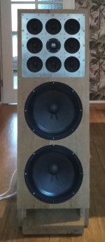
Two pictures of the build. When it is finished I'll try to make a few more.


Everything above 60 hz is coming from these...

Thank you for all your advice!
Regards,
hajo
It has been quiet for a while. I'v taken all the advice in consideration and finally opted for a array ripole with 4 12 inch car subwoofers. Because they are very flat with a reasonable high xmax.
Last week I had time to start the build. It is good it will be under the couch. Didn't become as neat as intended.
But never mind, today I got it hooked up and could give it a try.
I'm very pleased with the first results. I need to spend time to improve the response curve.
I post e screenshot. From my listening position in a living room which is far from ideal for a listening room. But that's what it is.
Two pictures of the build. When it is finished I'll try to make a few more.
Everything above 60 hz is coming from these...
Thank you for all your advice!
Regards,
hajo
Attachments
- Home
- Loudspeakers
- Subwoofers
- Bad news for Ripole sub builders :-(